
Introduction
After 6 years of 24×7 operation, the fan bearings in the Paul Novus 450 MVHR unit suddenly became very noisy and it was clear they needed replacing.
The official service manual says to replace the complete fan assembly (or both of them, if required), which would indeed fix the problem but would be incredibly wasteful and very expensive (I was quoted “about £280” for a replacement fan). A much better solution is to replace just the two ball bearing assemblies in each fan (roughly £10 per fan for the parts).
This is not a trivial procedure and requires more than the usual DIY tools, but it’s no worse than many car repair tasks, for example.
Motor and Bearing Specifications
Motor
The fan motors are fully integrated with the fan rotors and are made by ebmpapst in Germany. These are very well engineered units and well worth repairing. Part number G3G160-AD54-22 is marked on the motor housing but it’s not clear if that applies to the whole assembly of fan & motor together with the centrifugal flow casing or if it’s just for the fan & motor.
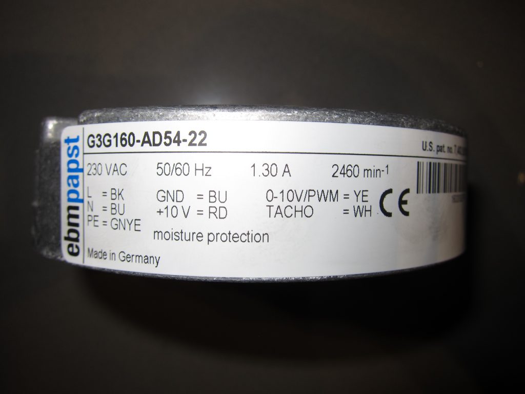
The motors have two electrical cables attached and the text on the motor label confirms the details of the wiring colour codes:
- One three-core cable provides the 230V AC mains supply:
- The Earth wire is Green/Yellow (GNYE)
- The Neutral wire is Blue (BU)
- The Live wire is Black (BK) rather than Brown as might be expected
- A separate four-core cable provides the control signals:
- The Blue (BU) wire provides a 0V (GND) reference voltage for…
- The Red (RD) wire provides a +10V output, to assist with…
- The Yellow (YE) wire provides a 0-10V input for speed control
- The White (WH) wire provides a tachometer output (two pulses per rotation)
- The Paul Novus calls this the “Hall” input, since it uses a Hall-Effect sensor
For bench-testing the motor, note that it is not sufficient to connect the mains supply; the motor will not run unless it also gets an input on the Yellow wire, to provide a target speed signal. (More on this below.)
Bearings
The original equipment bearings are made by SKF and have SKF Part Number 6000-2Z with a / +28 suffix. These have the following dimensions which the replacements must match exactly:
- Outside Diameter: 26mm
- Bore Diameter: 10mm
- Width: 8mm
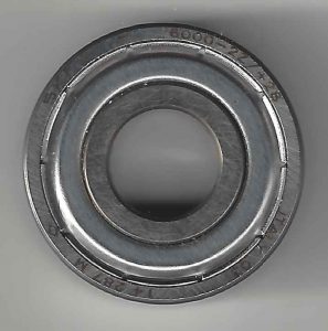
Note that these OEM bearings have a metal shield (that’s what the ‘Z’ in the part number signifies) on each side rather than a rubber grease seal, so they’re not as well protected from moisture as they would be with a seal – there’s a small gap between the shield and the inner race. A rubber seal does add a degree of friction and running costs are an important consideration for these systems so maybe it was a deliberate choice by the designers to optimise for low friction – at the expense of moisture tolerance.
While the OEM replacement bearing (i.e. SKF Part Number 6000-2Z) would be the obvious choice, where there’s evidence of premature bearing failure due to moisture ingress my recommendation is to replace with SKF Part Number 6000-2RSL instead; which has a “low-friction contact seal on both sides of the bearing”. In my case, SKF Part Number 6000-2RSH was available off-the-shelf from a local supplier so I used that instead (slightly higher friction, maybe? The ‘H’ signifies high-temperature tolerance which is not required but also not a problem).
Bearing Replacement Procedure
The first place to look for details of the repair procedure is the official servicing manual which provides advice on fault diagnosis and how to gain access to the fans (they’re behind the electronics assembly, which in turn is behind the white cover board with the wiring diagram).
With any repair like this, it’s a good idea to take several digital photos of the wiring layout and general set-up before removing anything – then it’s easy to check how wires should be connected and routed on re-assembly.
It’s necessary to cut the cable ties securing the fan cables (black) in order to create enough slack to pull the electronics assembly forward. Note the fan cables can be detached at the fans rather than at the circuit board – the black plastic moulding where the cables enter the fan is effectively a ‘socket’ that un-plugs from the fan itself – just remove the two T20 bolts holding the black plastic moulding in place and wiggle the moulding free.
The fan motors need to be detached from their aluminium housings anyway so it is best to leave the fan housings in place and just unscrew the circular mounting plate holding the fan into the housing – that way there’s no need to replace the NeoFermit non-setting gasket compound. Removing that plate creates a large enough gap for the fan motor and (larger) rotor to be removed.
For the bearing replacement procedure, there are some excellent videos on YouTube which show how to get the fan motor apart and extract the bearings. (These videos are not specific to the Paul Novus units but the same ebmpapst fans are used in a lot of similar ventilation systems.)
This first video shows a very ‘professional’ procedure using bearing puller tooling:
This second one is a bit more ‘diy’ but might also be useful:
A few supplementary notes from me:
- Replace the bearings on both fans at the same time – if one set have failed the others won’t be far behind and it’s much less hassle to do them both at the same time
- It’s important that the large, vertical semiconductor on the circuit board (with the big clips) makes good thermal contact with the aluminium heatsink – if either of them look a bit ‘wet’ that’s fine; don’t dry them
- The fan rotors will be dirty (especially the intake one) so take the opportunity to clean them – but take care not to dislodge the small ‘clips’ which are balance weights to reduce vibration
If you need to bench-test the fans, disconnected from the MVHR unit, they do require a control signal telling them how fast to spin – simply connecting the 230V mains is not enough. This is best achieved by wiring a 10 k ohm rotary potentiometer with a linear characteristic to the Red, Blue and Yellow control wires. See this page from ebmpapst for confirmation of the potentiometer specification and connection information.
As a final note, I unknowingly knocked DIP Switch 2 on the Fan Slave Board from On to Off while re-fitting the cable tie nearby – with the result that the fans didn’t even try to spin up and the unit reported “Error fan 2 Hall”. Another symptom was the green LED on the middle (pre-heater) control board flashing at about 1 Hz rather than being always-on. This had me puzzled for quite some time because I knew the fans had worked OK after the bearing replacement (I checked that before re-fitting the cable ties) and only careful reading of the service manual and checking my pre-disassembly photos highlighted my error.
![]() Paul Novus 450 MVHR Fan Bearing Replacement by Marsh Flatts Farm Self Build Diary is licensed under a Creative Commons Attribution-ShareAlike 4.0 International License.
Paul Novus 450 MVHR Fan Bearing Replacement by Marsh Flatts Farm Self Build Diary is licensed under a Creative Commons Attribution-ShareAlike 4.0 International License.
Hi David, just wondering if you’ve come across the problem with the Novus 450 not being in the EPC Product Characteristics Database (PCDB) when getting a replacement (RDSAP) EPC conducted? I have a client with one of these devices and this is the situation we are in, resulting in a lower EPC rating than we would like to achieve. Looks like the manufacturer has not paid for the Novus 450 to be tested and listed, but the Novus 300 is present, unless I’ve overlooked something. All the best, Piers
Hi Piers. Short answer: no, I’ve not come across that problem.
My original EPC was issued in 2017 so is still ‘current’. While I don’t have all the data behind that EPC, there’s an associated Regulations Compliance Report which includes some product-specific figures for Specific Fan Power and Heat Recovery Efficiency for the Novus 450, showing those were better than the Part L requirements.
My understanding is that the PAUL Novus product line got discontinued some time ago, so I don’t expect there will be any investment forthcoming from the manufacturer. The Novus 300 is very similar though (e.g. it takes the same filters as the 450) so there might be some scope to claim the listing for the 300 is applicable.
David
Many thanks for your reply David,
I decided to call Paul in Scotland this morning, and unfortunately they indicate they have no interest in getting the Novus 450 tested and listed in the PCDB, particularly as it’s a discontinued model, as you have indicated.
With RDSAP EPCs, there is unfortunately much less freedom to manually enter information, compared to how a full SAP EPC is conducted for new-builds. In fact for MVHR in RDSAP you can only select the device from the PCDB (plus some manual details of ducting insulation) or enter a generic option for MVHR which uses really bad efficiency information in the rating calculation.
The accreditation schemes will almost certianly fail an audit if the wrong model of unit is selected from the PCDB by a DEA, so we’re just going to have to accept the hit on the rating here.
This is likely to be a disappointment for many people with the Novus 450 when they get a new EPC, 10 years after construction.
I’ve seen this type of thing before though, for example a client approached me with an IVT ground source heat pump installed 10+ years ago, and none of their ground source products are in the PCDB either.
Anyhow, all the best for now,
Kind regards,
Piers