
Introduction
The Mechanical Ventilation with Heat Recovery (MVHR) system in the House generally needs little attention. These notes explain how the system is configured and what maintenance is required.
Configuration Notes
The MVHR unit for the House is a PAUL Novus 450 installed in the Plant Room. It is managed using the touch-screen controller mounted in the cupboard in the Utility Room (where any warning messages are slightly more likely to be noticed).
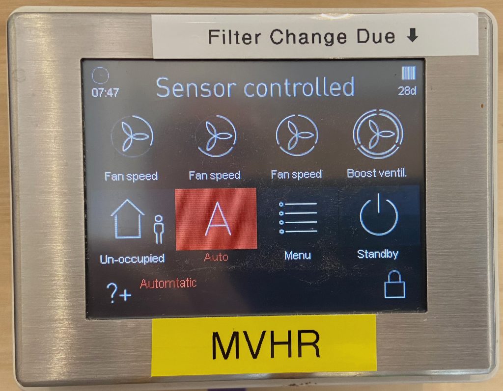
Normally the unit should be left in ‘Auto’ or ‘Sensor controlled’ mode which means that the fan speed is controlled by the Home Automation system’s ‘MVHR Fan Boost’ setting:
- A boost level of 0 corresponds to Fan Speed 1
- A boot level of 50 corresponds to Fan Speed 2
- A boost level of 100 corresponds to Fan Speed 3
The Building Regulations requirements for ventilation in each bathroom are met at Fan Speed 2 – but unless all bathrooms are in use this delivers excessive ventilation and something closer to Fan Speed 1 is often adequate, although CO2 levels in bedrooms will typically exceed 1000 ppm by the end of the night at Fan Speed 1. Experience shows that a boost level of around 25% works well; If required, a short boost at a higher speed will help to clear steam or smells.
In very hot weather it can be beneficial to set the speed low during the hottest part of the day, to reduce the tendency for the MVHR to bring in hot air, then set the speed high overnight to help to purge the heat.
When the unit was new it was fitted with a ‘standard’ heat exchanger but this was replaced with an ‘enthalpy’ heat exchanger in July 2018:
- The ‘standard’ heat exchanger allows heat to flow from the incoming to the outgoing air but it blocks any transfer of moisture. As a result, when the incoming air is dry (such as in the winter) the ventilation will tend to result in low humidity inside the house – especially if there are only a few occupants.
- The ‘enthalpy’ heat exchanger allows the transfer of both heat and moisture, so it slightly helps to maintain healthy levels of humidity inside the house.
The original heat exchanger is in a box in the Plant Room and can be reinstated if the humidity preservation by the ‘enthalpy’ heat exchanger becomes a problem.
Regular Mainternance
Filter Change
The main maintenance task is the filter change, which needs to be done about every 6 months. 1st April and 1st October works well; harvest time can be dusty so it’s best to change the filters relatively soon after harvest in the adjacent fields has been completed. A quick vacuum clean of the filters at the half-way point doesn’t hurt.
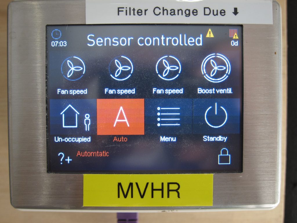
The Control Panel displays a count-down indicator in the top-right corner, showing in how many Days the filter change is due. This changes colour as the deadline approaches.
There is an F7-grade (fine) filter on the air intake from outside and a G4-grade (coarse) filter on the air extract from the house. These are available as a paired set. While there is a smaller (Novus 300) and larger (Novus 450) model in the PAUL model range, they all take the same-sized filters.
The F7-grade filter will trap pollen and some particulate air pollution so is a good choice to filter the outside air – even though it creates more air resistance which needs more fan power to overcome it. The G4-grade is a coarser filter – but really all that’s doing is keeping dust generated inside the house away from the heat exchanger, before the extract air is sent outside. For more information about the performance of the various grades of filter see Air Filter Classification and Grades.
The fans need to be turned off while replacing the filters, so the unit should either be placed into ‘Standby’ mode via the Control Panel or completely turned off at the mains. (This is a good opportunity to Test the operation of the RCBO circuit breaker – no. 6 in panel DB/3, labelled “MVHR UNIT”.)
After the filters have been changed the control panel touch screen needs be used to reset the filter change countdown:
- Press ‘Menu’ (twice) to enter the “Informations” screen
- Press the Down Arrow (⌵) to highlight the “Settings” option
- Press the ‘Enter’ button (↩) to access the “Settings” screen
- Press the Down Arrow (⌵) to highlight the “Filter” option
- Press the ‘Enter’ button (↩) to access the “Filter” screen
- Press the white box towards the bottom right of the screen, so this shows a ‘tick’
- Press the ‘Enter’ button (↩) to reset the filter change reminder
- Press ‘X’ three times to exit back to the normal view
The best place to buy replacement filters is “21 Degrees” (what used to be the Green Building Store): Filter for Paul Novus MVHR and the cheapest option is to buy sets of 10 filters of each grade – i.e. 5 years’ worth.
Heat Exchanger Cleaning
While not strictly necessary if filters have been changed on a regular basis, some people recommend the heat exchanger should be washed every five years or so.
Miscellaneous Notes
Fan Bearing Replacement
Some of the fan bearings failed in autumn 2022 and were all (2 bearings on each of 2 fans) replaced. While only the bearings on the intake fan had actually failed (being more exposed to cold and damp outdoor air) it always pays to replace them all at the same time. More details on this page.
The replacement bearings have rubber seals and should be slightly better at resisting corrosion than the originals. Maybe they’ll last 8 years, rather than 6 – so expect to replace again in about 2030???
Control Panel Cabling
The wired connection between the MVHR unit and its touch-screen control panel uses standard ‘Ethernet’ cabling but this is not a TCP/IP network connection. It uses a proprietary protocol (based on RS-485). This does mean the control panel can be located anywhere there is a nearby network socket – as long as the socket near the MVHR unit (Patch Port 118) is cross-patched to the location of the control panel, using the patch panel in the Comms Room. Purple Ethernet leads are used to distinguish these cables from other network cables, but there is nothing special about the specification of these cables.
Note that the MVHR unit must be power-cycled to re-pair it with the control panel if any of these cables are disconnected.
0-10V Control Input
In ‘Auto’ mode, the fan speed varies between Level 1 and Level 3 depending on the voltage present on the 0-10V input (0V = Level 1; 10V = Level 3). This control voltage is generated by an Osram-branded DALI to 0-10V converter mounted in the trunking near the alarm control box in the Plant Room. The output from this is connected to the MVHR unit with a bright green (‘KNX’) cable but this is not a KNX signal, just an analogue voltage.
MVHR Temperature Monitoring
One annoyance with the PAUL Novus models is that there is no easy way to get access to the data from their internal sensors. There is no published interface by which to access the data and these units don’t connect to the Internet. Some people have had a degree of success reverse-engineering the RS-485 control bus protocol used between the main unit and the control panel(s) – see e.g. https://github.com/BenPru/novus300_Rs485 and https://github.com/Schack17/PaulFocusNovus/wiki/RS485-Bus-Paul-Novus-300-(Focus-200)
As a workaround, the MVHR ducts were retro-fitted with separate temperature sensor probes, as documented in this separate article. These sensor readings are ‘polled’ on a regular basis and published as MQTT messages.
![]() Plant Room – MVHR by Marsh Flatts Farm Self Build Diary is licensed under a Creative Commons Attribution-ShareAlike 4.0 International License.
Plant Room – MVHR by Marsh Flatts Farm Self Build Diary is licensed under a Creative Commons Attribution-ShareAlike 4.0 International License.