
Introduction
KNX home automation installations use characteristic bright green ‘TP1’ cabling to form the KNX ‘bus’ that devices connect to. This cabling normally1 consists of two twisted pairs (red/white and yellow/white) plus a ground/drain wire – all protected by a foil screen enclosed within a tough outer sheath. On simple installations, all KNX devices connect to the same electrically-continuous ‘bus’ cable – usually in daisy-chain fashion.
There are however limits to the use of a single cable:
- On modern KNX installations there’s a hard limit of 256 devices per ‘line’ (it used to be 64 on older installations)
- In KNX installations spanning separate buildings, best practice is to separate the KNX cabling in some manner
- In practice, the real-world limit is normally imposed by the size of the KNX bus power supply, with the smaller models only providing enough power for 10 or 20 devices2
KNX has robust mechanisms for addressing these limits, with the possibility to form a hierarchy of multiple cable segments connected in a well-managed fashion. The two main options when a single cable is no longer appropriate are:
- Directly linking two segments of the same type of Twisted Pair cable via a KNX Line Coupler which applies two ‘types’ of isolation
- Electrical isolation, using a transformer to ‘couple’ the data communications on each side while isolating the DC power (hence each line needs its own power supply)
- Address isolation, by controlling which KNX addresses should be replicated across the coupler
- Using a TCP/IP network as the ‘backbone’, connecting KNX IP Router devices on each bus segment to propagate KNX datagrams between them as Multicast traffic over TCP/IP
- Again there is a degree of control over what KNX traffic remains ‘local’ versus what is sent to the ‘other’ cable – and of course there is inherent electrical isolation too
It makes sense that the KNX system designers chose Multicast as the IP technology for connecting multiple KNX IP Routers together: on a simple IP network, any number of KNX IP Routers will automatically ‘see’ each other, with no further IP configuration being required. The default KNX Multicast address (224.0.23.12) and IP port number (3671) have been officially registered with IANA.
The complication is that if multiple KNX IP Routers are not all on the same IP Subnet, Multicast traffic does not automatically propagate between them. This is by design: a key principle of Multicast is that packets only get sent to devices that are interested in receiving those packets – and an IP Router does not magically know whether any upstream or downstream routers might have such an interest.
Option 1 – Single IP Subnet
One option is to contrive for all of the KNX IP Routers to be on a single IP Subnet – for example by using Ethernet Bridge devices to connect multiple (logical) Ethernet segments to form a single Subnet which then propagates Multicast (and Broadcast) traffic to all connected devices.
Option 2 – Broadcast Relay Software
On installations which have multiple IP Subnets connected to a single IP Router, an option is to run software on the Router which (selectively) replicates packets between those Subnets. Typically, such software will be referred to as a ‘UDP broadcast relay’. (Multicast traffic is always UDP since TCP mandates a single Source and a single Destination, which is not the case for Multicast traffic.)
Where a site has more than one IP Router, it is also possible to replicate Multicast packets between the Routers by running ‘broadcast relay’ software on each IP Router – so that they form a ‘chain’ which forwards Multicast packets.
Option 3 – Multicast Routing
The ‘official’ way to do this is to use Multicast Routing protocols to advertise that particular Routers need to propagate particular Multicast addresses. The preferred choice of Multicast Routing protocol seems to be Protocol-Independent Multicast (PIM) which is implemented in several routing software packages:
The ‘Protocol-Independent’ aspect of PIM is that it relies on accurate unicast routing tables being maintained by a router but it doesn’t care how those are generated – e.g. whether they were derived using BGP, OSPF or other routing protocols (or even specified as static routes, presumably).
Selected Configuration – Option 2
For a relatively simple site with only two buildings and a fixed set of Multicast requirements, it seemed easiest to use a two-router implementation of ‘Option 2’ (Broadcast Relay Software).
UDP Broadcast Relay Software
The two routers are running the OPNsense network security software. There is an optional UDP Broadcast Relay plugin available for OPNsense which is based on https://github.com/udp-redux/udp-broadcast-relay-redux (which is now in an ‘archived’ state). The plugin needs to be installed – and then configured – on both routers.
Network Topology
The ArchiMate diagram below shows how the key components fit together:
- There are two Buildings, each with their own KNX Router, local TCP/IP Network subnet and TCP/IP network Router
- The two TCP/IP network Router devices are connected via a separate ‘backbone’ network subnet
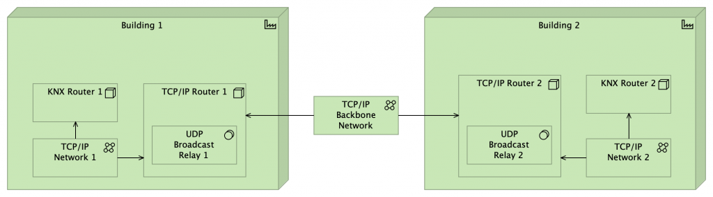
The way this works is:
- KNX traffic originating from KNX Router 1 is Multicast to all devices on TCP/IP Network 1 – including TCP/IP Router 1
- UDP Broadcast Relay 1 sees the incoming KNX traffic and propagates this as Multicast to its defined set of other TCP/IP networks – including the TCP/IP Backbone Network
- UDP Broadcast Relay 2 see the incoming KNX traffic and propagates this as Multicast to its defined set of other TCP/IP networks – including TCP/IP Network 2
- KNX Router 2 receives the relayed KNX traffic
UDP Broadcast Relay Configuration
Simply installing the UDP Broadcast Relay plugin has no effect. An instance of the Relay has to be configured (on each TCP/IP Router) with the relevant network properties:
- The ‘KNX’ UDP port number: 3671
- The ‘KNX’ Multicast address: 224.0.23.12
- The set of network interfaces to relay traffic between
- A unique UDP Broadcast Relay ‘Instance ID’
- These have to be different for the two relays – any incoming packets with a matching Instance ID are not forwarded (since they’re assumed to be duplicates) so in order for Relay 2 to propagate packets from Relay 1, the IDs need to be different
Firewall Rule Requirements
Depending on the strictness of the firewall configuration on the two TCP/IP Routers, it might be necessary to add firewall rules to allow the traffic to flow. A good way to understand whether firewall settings might be blocking traffic is to run the UDP Broadcast Relay from the command-line, in verbose mode, which will show error messages (or fail to show packets arriving and being forwarded).
Network Switch Configuration
Where a Multicast (IGMP) aware Layer 2 switch is in play, the first challenge is getting that to propagate Multicast traffic out of the switch and into the router.
Netgear
Netgear managed switches provide quite a number of configuration options for Multicast, managed via the Web UI under: Switching > Multicast
If “IGMP Snooping Status” is set to “Disable” then no attempt is made to filter Multicast traffic and it should be propagated without restrictions.
If however “IGMP Snooping Status” is set to “Enable” then further configuration is required to specify what behaviour is required.
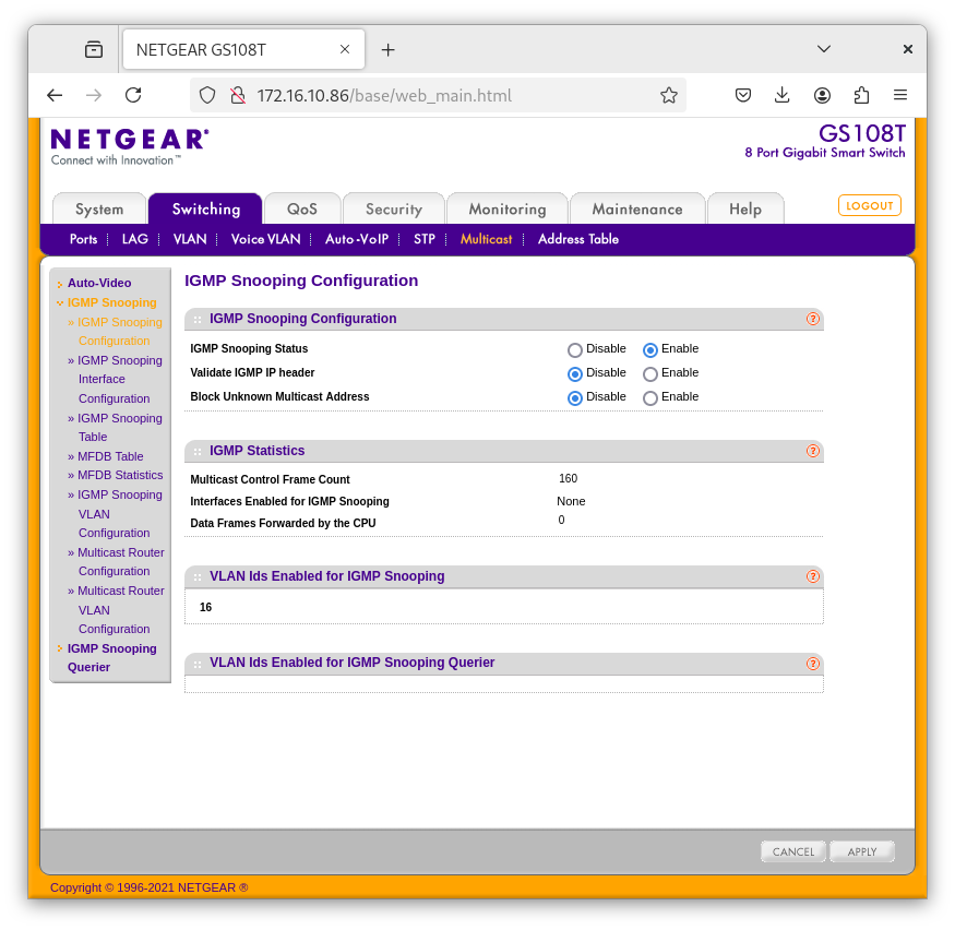
As with many of the Netgear configuration settings, Multicast traffic handling can be specified on an “Interface” basis or against other criteria – a key one being VLAN.
It’s necessary to specify which VLANs should have IGMP Snooping enabled – and what other configuration settings apply.

That covers the propagation of Multicast traffic between machines connected to the same switch which all advertise Multicast group membership via IGMP. However, an upstream Multicast Router needs to be specified separately.
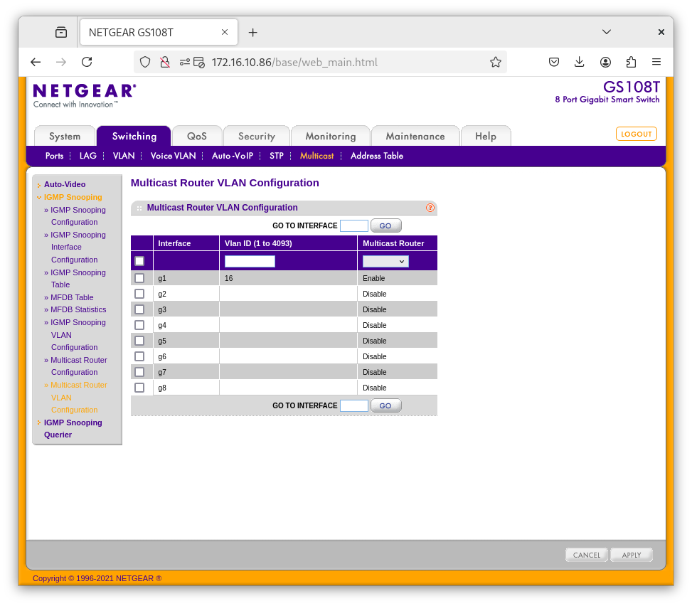
Together, these settings get Multicast traffic (on VLAN 16) forwarded to and from the upstream Multicast Router.
Ubiquiti UniFi
With Ubiquiti UniFi network switches, the situation is broadly similar – except that IGMP Snooping is enabled by default, for all VLANs.
The Multicast configuration is summarised in the Settings > Network page of the management console. The important thing is to ensure the Uplink switch ports – to the Router (or another Switch) are specified as ‘Multicast Router’ ports for the VLANs which are known to be carrying Multicast traffic. This is specified on the configuration page for the relevant Switch Ports.

Further Reading
- A guide to using KNX over IP from Ivory Egg.
- https://simonhackett.com/2020/09/14/knx-tips-and-traps-part-2-knx-ip-routing/
- A variant containing just one twisted-pair is also available, which tolerates a tighter bend radius but is only recommended where that is especially important – typically within equipment racks ↩︎
- Though of course this depends on the power consumption of each device. Some of them – e.g. PIR sensors – might only have a nominal consumption of 3mA but others – e.g. IP Router devices – might want 40mA ↩︎
![]() KNX IP Routing Communications using TCP/IP Multicast by Marsh Flatts Farm Self Build Diary is licensed under a Creative Commons Attribution-ShareAlike 4.0 International License.
KNX IP Routing Communications using TCP/IP Multicast by Marsh Flatts Farm Self Build Diary is licensed under a Creative Commons Attribution-ShareAlike 4.0 International License.