
Introduction
I’m keen to understand the behaviour and performance of the Mechanical-Ventilation-with-Heat-Recovery (MVHR) system, in particular the relative temperatures of the incoming and outgoing air flows and the impact of the duct heater. It’s frustrating that the PAUL Novus 450 MVHR unit is doing its own temperature monitoring (and also knows the flow rates and the fan power settings) but it doesn’t provide any mechanism to access the data. The manual says that the unit is using RS-485 for its internal communications (e.g. between the main unit and the external touch-screen control panel) but also includes a warning not to try to connect to this.
The answer is therefore to install some retrofit temperature sensors into the ducts, query those on a regular basis and log the data somewhere safe where it can be accessed relatively easily for display purposes.
Product Selection – Temperature Sensors
Air temperatures need to be measured within each of the ventilation ducts:
- Fresh air Intake from outside
- Stale air Exhaust to outside
- Fresh air Supply to inside
- Both upstream and downstream of the duct heater
- Stale air Extract from inside
That’s five locations in total. The temperature sensors need to sit in the airflow without causing too much of an obstruction, so they need to be relatively small.
Specialist duct temperature sensors are available from the major HVAC equipment manufacturers but those tend to be expensive and for simple monitoring (rather than control) a cheaper and simpler alternative is more appropriate.
The Dallas Semiconductor 1-Wire temperature sensors are very widely used and have excellent support for integration with embedded micro-controllers like the Arduino or Raspberry Pi. The DS18B20 sensor chips are available as bare ICs or sealed into a stainless steel tube with a flying lead, which are very suitable for duct installation. These are readily available via eBay – simply search ebay.co.uk for “ds1820b waterproof”. At the time of writing they’re slightly over £1 each when bought direct from China.
The stainless steel tube is 6mm diameter, 50mm long and roughly half of the tube is covered with heat-shrink. A “6mm” rubber grommet is a slightly loose fit on the bare tube but a nice tight fit over the heat-shrink. The grommet fits into a 10mm hole in the duct. Sensors with the grommet attached and removed are shown below.
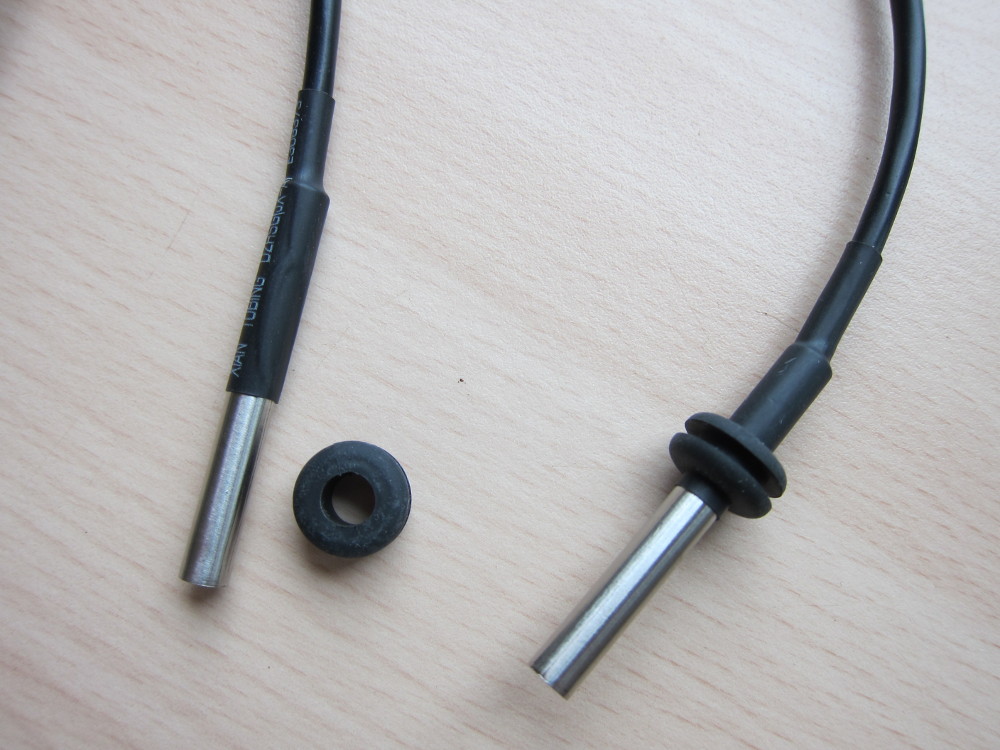
DS18B20 Temperature Sensor in Stainless Steel tube
Each sensor has a unique ID code so multiple sensors can be attached to a single 1-Wire bus and still interrogated independently by specifying the relevant ID code. The analogue temperature is converted to a digital signal within the sensor chip so the length and resistance of the cables doesn’t affect the accuracy of the reading.
Product Selection – 1-Wire Host Adaptor
I’m already running a Raspberry Pi (an old Model B) to collect data from the M-Bus meters so it makes sense to have that same device collect the 1-Wire data as well. It is possible to connect 1-Wire devices directly to the GPIO pins on the Raspberry Pi but there are some limitations with doing that. A better solution is to use a 1-Wire Host Adaptor circuit and there’s a good list of the various options for those on the Sheepwalk Electronics website. I opted for their middle-of-the-road RPI2 variant and bought the kit of parts to solder up myself (the surface-mount ICs were a bit fiddly though).
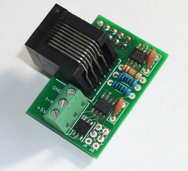
RPI2 1-Wire Host Adaptor Board
Photo from http://www.sheepwalkelectonics.co.uk/
The RJ45 socket isn’t for an Ethernet connection; instead it lets you use standard patch leads for connecting up the 1-Wire bus. Alternatively you can connect to the terminal block (or both). By buying the kit of parts and soldering yourself you could omit the RJ45 socket if you’re not using it, which reduces the physical size of the board significantly.
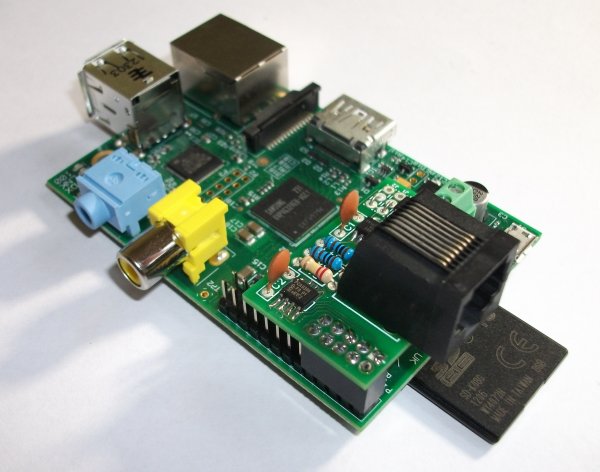
RPI2 1-Wire Host Adaptor mounted on Raspberry Pi
Photo from http://www.sheepwalkelectronics.co.uk/
Hardware Installation and Cabling
My Raspberry Pi is going to live in an Italtronic DIN Rail mount case and I cut a hole for the 1-Wire RJ45 socket as shown below. Making the hole a close fit provides mechanical support to the board as well, since otherwise it’s just cantilevered off the GPIO pins.
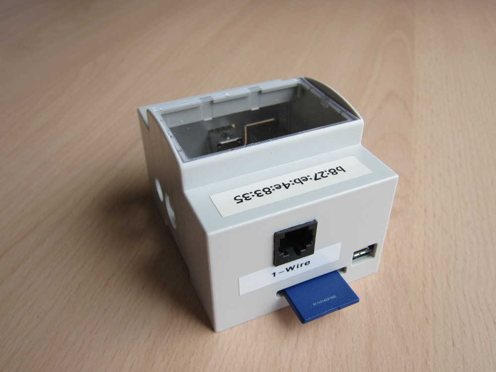
Raspberry Pi with RPI2 Adaptor mounted in DIN Rail Case
The next problem is connecting 5 of the 1-Wire sensors to the bus, which is neatly solved by using a break-out box from the OpenEnergyMonitor online shop. The OpenEnergyMonitor people specifically state that they use the same RJ45 wiring convention as Sheepwalk Electronics, which makes for easy plug-and-play. I mounted the break-out box in a protective case – shown here with just one of the sensors connected. The case is 85mm x 58mm x 35mm.
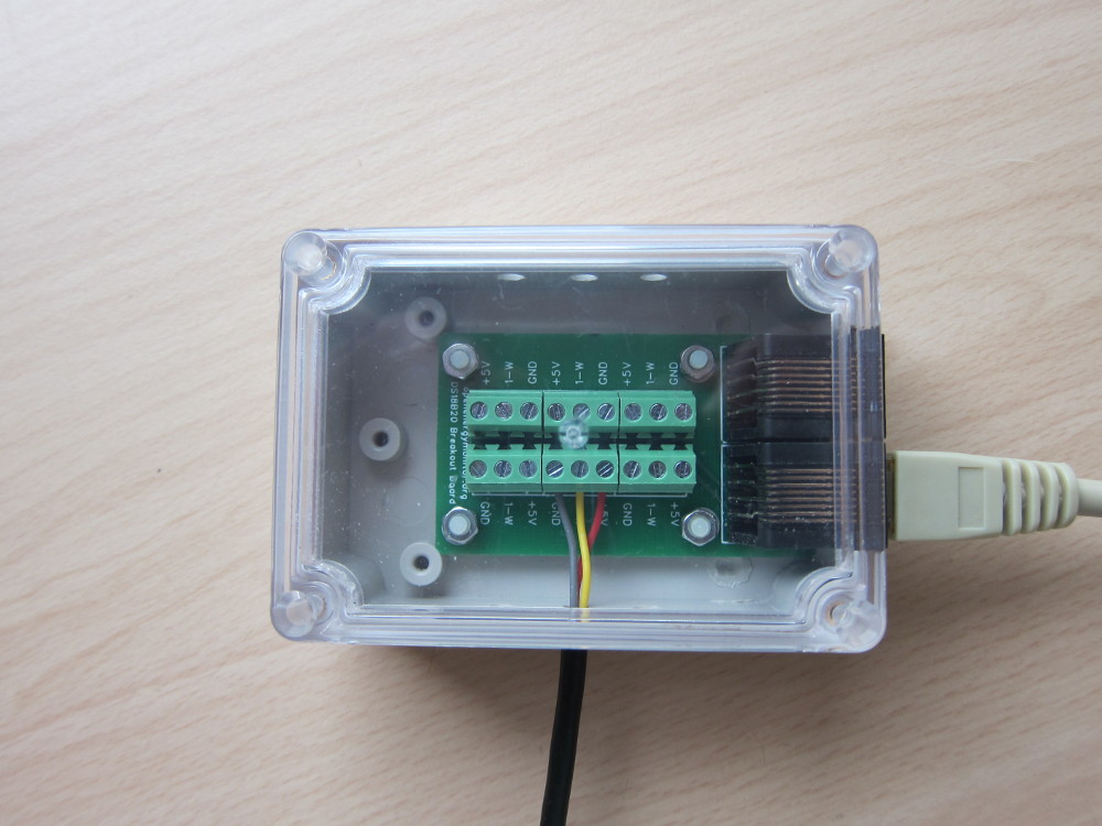
OpenEnergyMonitor 1-Wire Break-Out Box mounted in case
For the final installation the sensor wires will go further into the case and I’ll add a cable tie to each as a crude form of strain relief.
The colour code for these pre-wired sensors seems to follow a standard convention.
- Red is the +5V power supply
- Yellow is the 1-Wire data signal
- Black (or grey in my case) is the ground
The completed installation (for bench testing) is shown below.
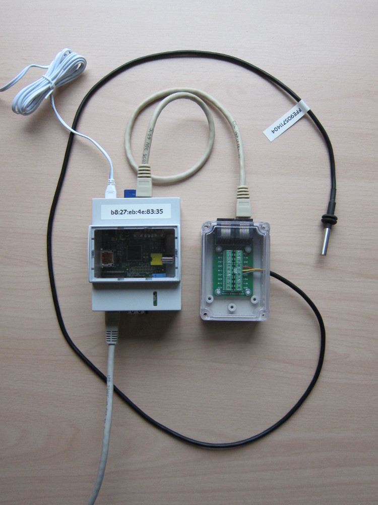
Completed installation with one sensor
Since the data gets read in terms of the unique ID codes of each sensor it’s important to know which one is which! This is best done by connecting each one to the bus in turn and checking its ID – and then adding a label like the one in the photo.
2016-06-26 Update: A refinement to this installation is to provide power to the Raspberry Pi via Power-over-Ethernet (PoE). Since the power requirement is so low it seems a waste to have to use a 13A socket with an individual 5V DC power adaptor and for other devices I’ve had good success using the D-Link DWL-P50 PoE splitters which convert the 48V DC PoE supply into something more standard. (It’s not possible to use a simple DC-DC converter since a PoE switch will only send the 48V DC if it completes some sort of handshake with the PoE device.)
The D-Link website shows that the DWL-P50 is being “phased out” but they’re still being sold by UK retailers and you can pick them up on eBay reasonably easily – used ones can be a good price (whereas new ones can be ridiculously expensive). An alternative is the TP-LINK TL-POE10R which I haven’t tried but looks comparable.
The DWL-P50 has a switchable output for 5V or 12V (the TL-POE10R also has the option of 9V) and comes complete with a DC power lead which has 5.5mm / 2.1mm DC plugs at both ends. To connect to the Raspberry Pi use a Micro-USB to 5.5mm / 2.1mm adaptor lead like this one from eBay.
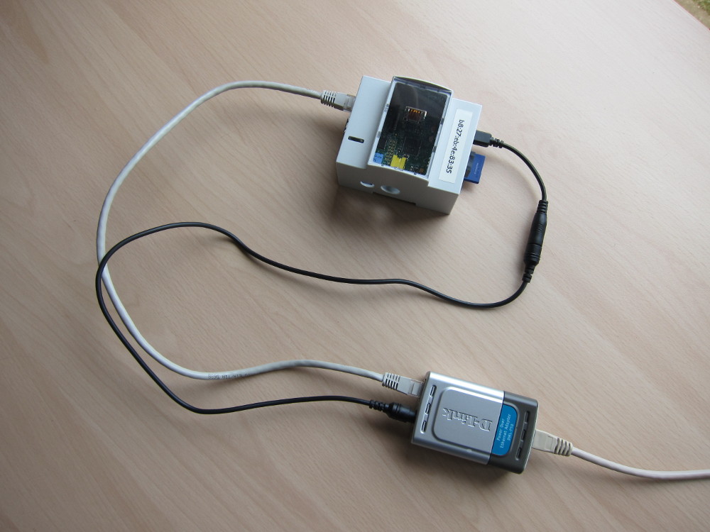
Raspberry Pi powered by PoE using a D-Link DWL-P50 PoE Splitter and a DC-to-USB cable
The result isn’t quite as tidy as for a device with built-in PoE support but it’s better than using a separate mains adaptor. Some models of network switch provide an option to power-cycle the PoE on a particular network port via the switch’s administration console, which in principle lets the device be power-cycled remotely.
2016-10-14 Update: Everything is now installed and working. It wasn’t that easy to fix the junction box to the Armaflex-insulated ducts so I strapped it on with nylon cord. The black CAT5E cable connects back to the Raspberry Pi and the grey one is an extension cable for the temperature sensor monitoring the heated supply air, which is further away. The other four sensor probes connect directly, plus I added a further one for the ambient temperature in the Plant Room; six in total.
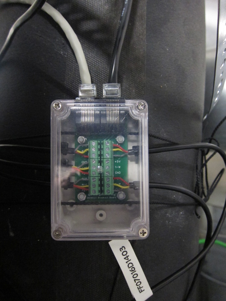
MVHR Temperature Sensor junction box
Software for Reading the 1-Wire Sensors
The 1-Wire Host Adaptor presents the 1-Wire data via the I2C bus and then the One Wire File System (OWFS) utilities make it accessible from the command-line. There’s an information page for RPI2 software on the Sheepwalk Electronics website and following the instructions there worked perfectly. Reading the data from a sensor is as simple as:
$ owget 28.FFE9D5711404/temperature ; echo
       18.75
(the “echo” command is only there to add a newline character since one isn’t added by default)
Software for Publishing the Temperature Data
The temperature data from the MVHR ducts needs to be integrated into a wider suite of monitored parameters for the house:
- I have some portable indoor temperature sensors (Oregon Scientific THN132N) which will be placed in different rooms to monitor temperature variations in different locations. These transmit via radio at 433MHz and the data will be collected via an RFXCOM receiver.
- If I was purchasing these sensors now I’d probably opt for a solution from the excellent OpenEnergyMonitor project but since I have already invested in the Oregon Scientific sensors and an RFXCOM receiver I will continue to use those.
- There is other temperature-related data coming from the Ground Source Heat Pump and the heating control system which it will be interesting to compare with the rest of the temperature data.
- The NIBE F1145 heat pump will be reporting its operational parameters via NIBE Uplink and the plan is to extract data via their API and publish alongside the other temperature data.
- The underfloor heating system has temperature probes located in conduit embedded in the concrete floor slab and these are reporting temperature data via the KNX bus.
In total that’s four different sources of temperature data (with the likelihood of adding more at some point). Once the data has been collected, the specific technology used (1-Wire, RFXCOM, KNX etc.) is irrelevant and so all the data should be brought together under one umbrella. For that I’ve decided to use MQTT.
Technology-wise, MQTT isn’t too bad – Mosquitto is the de-facto standard message broker for small installations – but all of the parameters sit within a single, hierarchical “topic structure” which warrants some design:
- It seems almost universal for the leaf nodes in the topic structure to reflect the type of parameter being monitored (temperature, humidity, battery charge level etc.)
- The higher levels in the topic structure can either represent physical locations (rooms in the house), or systems (such as the ventilation system or the heating system), or the underlying device technology and its native identification scheme (1-Wire sensor IDs, Oregon Sensor IDs (which change when you reset them after a battery swap) etc.) or some other naming scheme.
At the risk of making things too complex from the outset, I can relate to some of the observations from others facing the same challenge who concluded it was best to initially publish the data with its raw, native, concrete identification and then to re-publish under one or more aliases. See in particular:
- MQTT: about dumb sensors, topics and clean code which is a blog post from Robert Hekkers in 2012, proposing a basic approach
- MQTT Republishing Itch which is a follow-on post from Kyle Gordon who has posted his re-publishing code at https://github.com/kylegordon/mqtt-republisher
- MQTT topic naming convention which is a blog post from Xose Pérez where they explain they’re not convinced about re-publishing and prefer to implement a mapping before publishing in the first place
Personally I can see a possible use case for re-publishing under multiple schemes (is the MVHR duct heater part of the ventilation system, the heating system or both?) and I’m not bothered about the network traffic impact by a bit of re-publishing.
TODO: The next step is to query the temperatures periodically (easy enough using “cron”) and then publish the data somewhere:
- The current plan is to use MQTT to send each temperature reading to a message broker (Mosquitto)
- Adapt this simple publish-owfs-mqtt.sh script to do that?
- I’m considering using Emoncms (from the OpenEnergyMonitor project) for storing the results, and maybe also for graphing via their dashboard facilities
- There’s already an MQTT interface into Emoncms
- Another option is to use a general-purpose time-series database with a general-purpose graphing engine
- Alternatively (or as well) there’s an MQTT binding for openHAB which is currently my preferred Home Automation software solution
References
https://openenergymonitor.org/emon/buildingblocks/DS18B20-temperature-sensing
![]() MVHR Temperature Monitoring by Marsh Flatts Farm Self Build Diary is licensed under a Creative Commons Attribution-ShareAlike 4.0 International License.
MVHR Temperature Monitoring by Marsh Flatts Farm Self Build Diary is licensed under a Creative Commons Attribution-ShareAlike 4.0 International License.
Hi, Thank you for this brilliant article on how you are monitoring the MVHR system, I’ve copied it almost exactly, it’s really useful. I also have a Paul Novus and found the bypass system a bit restrictive, it would be very nice to be able to control it from the RPi, it should be very simple to do, did you ever manage to contact Paul and gain access to the system?
Hi Brian,
Thanks for the feedback and glad you found the info useful.
I don’t mention it in this article but I do have a 0-10V input hooked up to the unit which gives a degree of control over the fan speed – basically it’s on Speed 2 at 0V and Speed 3 at 10V with infinite variation in between (replacing a dedicated ‘boost’ button). The 0-10V signal comes from a DALI lighting dimmer which is part of the Home Automation system.
I didn’t ever contact Paul – they’re part of Zehnder these days and I got the impression the Paul Novus product line wasn’t being actively developed (just a hunch so could be completely wrong!).
I do know that the bypass settings are configurable, to some extent. I remember seeing some documentation about the logic used; should be able to dig out the manual if you’ve not seen that already.
David
Hi David
I did contact Zehnder about controlling the bypass system via an external system, they said that access to the bypass system isn’t possible.
I found that on a cold sunny day like we’ve had this April, solar gain builds up the internal temperature in the house but the bypass remains closed because the external temperature is below the minimum value set as default in the system. I’ve managed to plot some interesting graphs that shows when the bypass opens and closes, the adjustment provided via the control panel doesn’t actually change the temperature it opens or closes.
I’ll send you plots of the graphs if you have an email address I can use.
Brian