
Introduction
The House has an existing Solar PV installation, consisting of 20 x 270W panels (i.e. a nominal total of 5.4 kWp) and a 5kW SolarEdge inverter. The DNO approved up to 5.4 kW of Export, so this installation runs with no need to manage any export restrictions; even if the House is using no power the Solar PV installation cannot possibly exceed the site export limit (and generally the House is always consuming a few hundred watts anyway).
The Outbuildings are getting a new Solar PV installation consisting of 24 x 460W panels (i.e. a nominal total of 11.040 kWp) connected to a new Tesla PowerWall 3 inverter and battery. The existing Solar PV installation on the House will remain as-is – however, the site export limit remains in force, so now that needs to be actively managed – and that management is done by the controller within the PW3. While the PowerWall can’t change what generation is coming from the existing installation1, it does need to know what that is – so that it can account for it as part of the site generation totals (and – if necessary – curtail its own solar generation to stay within the limits – there’s a built-in meter which knows how much the PW3’s own solar inverter is generating)).
As a result, some sort of ‘metering’ needs to be connected to the existing solar PV system.
Option 1 – Tesla Remote Energy Meter
With earlier versions of the PowerWall hardware Tesla used a third-party ‘Neurio’ energy meter but for the PowerWall 3 they have their own, Tesla-branded Remote Energy Meter. The ‘remote’ aspect is that it can be installed some distance from the PW3 and the Backup Gateway.
The Remote Energy Meter uses 200A CT clamp(s) but then transmits the measured reading to the PowerWall 3 (rather than the Backup Gateway) using some other protocol:
- Over a WiFi data link, or
- Over an RS-485 serial link
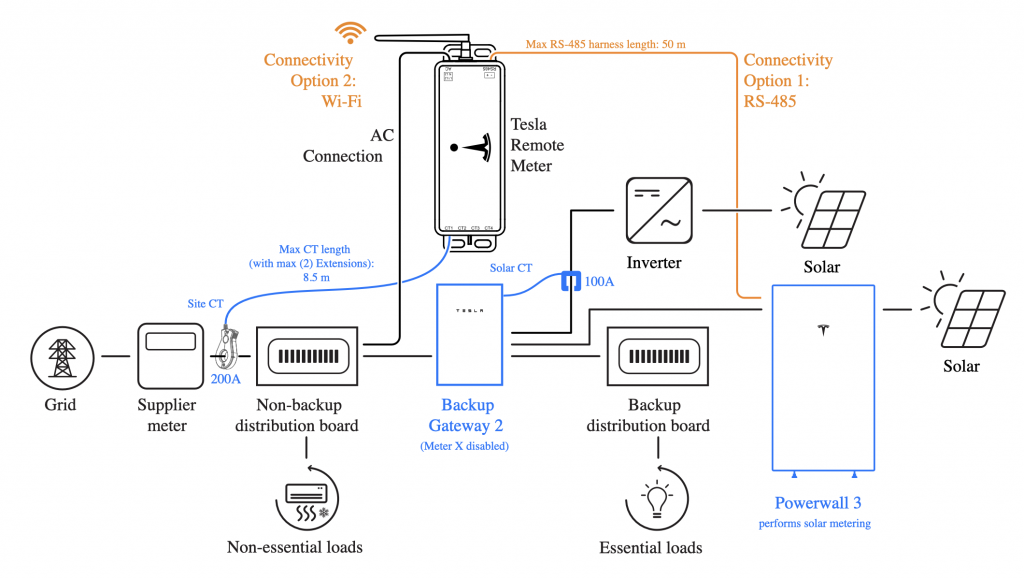
It’s not clear from the standard Tesla documentation exactly how the WiFi connection is established (e.g. which SSID it uses) but Tesla Technical Support advised the remote meter connects to the PowerWall 3’s built-in WiFi subsystem. The meter has a WiFi antenna (with some scope to mount that outside a metal enclosure) but it connects to the built-in antenna on the PW3, which is normally only used for commissioning. It does not rely on the ‘site’ WiFi (even though that is how the PW3 would connect to the Internet when using WiFi, rather than a Wired Ethernet connection) – which means there is little scope to improve the WiFi signal strength using additional Wireless Access Points. It’s not clear how effective such a WiFi connection might be without experimenting on-site and testing the impact of foil-faced insulation boards and other RF barriers along the communications path.
In cases where the WiFi link proves unreliable, the RS-485 serial link is available as an alternative – although the above diagram notes this has a cable length limit of 50m (which is too short). Assuming this is ‘standard’ RS-485 then the cable length limit could be addressed using a pair of RS-485 network ‘extenders’ which use a TCP/IP connection for the majority of the distance. These are also known as ‘serial device servers’ and examples from Waveshare are very affordable; about £20 each (with two being required).
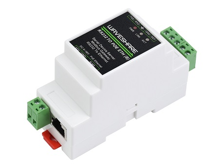
These serial device servers require a DC power supply – or a variant is available which uses Power-Over-Ethernet (POE), which is generally preferable. However, that’s all getting a bit complicated since the end-to-end communications path would have a reliance on the Ethernet Switches in each building, their associated Network Routers and the related communications links – all of which need power supplies.
Option 2 – Built-In CT-Based Metering
The Tesla Backup Gateway has two built-in energy meters:
- ‘Meter X’ is configured to measure the whole site import / export via a built-in CT – i.e it is metering the connection to the supplier meter and thus seeing everything that the site is importing or exporting
- It uses this meter to enforce the site export limit
- ‘Meter Y’ is available to measure at various locations using a remote CT clamp, wired back to the Backup Gateway
- A typical configuration is to use this to meter a third-party, AC-connector solar inverter, as shown in the diagram below
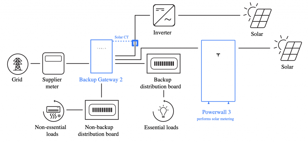
Since the remote CT clamp must meter only the AC-connected inverter, it needs to be connected relatively close to that inverter – which is on the second floor of the House. However, there’s a dedicated mains cable which runs down to the ground floor of the House, connecting the inverter to the House’s main distribution board, so the CT clamp can be installed there. That’s a 90m cable run from the Backup Gateway location.
When extending CT cabling for other systems it is customary to use one of the twisted pairs within a Cat 5E or Cat 6 network cable but the Tesla manuals are very specific about the requirements for CT extension cables and only tolerate the use of 0.2mm2 (24 AWG) Cat 5/6 cabling for CT extensions up to 15m. Beyond that length, up to 100m, they mandate the use of at least 0.5mm2 (20 AWG) twisted pair cabling.
Selected Configuration
The installer’s initial proposal was to use the Tesla Remote Energy Meter and have that connect to the PowerWall 3 using WiFi, but given the understanding that relies on the built-in WiFi for the PW3 it’s not clear how reliable that would be. Using the RS-485 link for the Remote Energy Meter might be OK – assuming that using an over-specified extension cable would increase the 50m cable length limit to 90m, or by extending the RS-485 link with a pair of TCP/IP extenders.
On balance, it seemed better to keep things really simple and just extend the CT leads from the Backup Gateway, doing away with the cost and complexity of the Remote Energy Meter. By prudent choice of the CT extension cable it might be possible to re-purpose this for RS-485 connection instead. Using a cable equivalent to Belden 8760 (18 AWG, Screened, 1-Pair with an External / Duct-Grade Sheath) will exceed the requirements – since for CT extensions Tesla only require 20 AWG (and 18 AWG is ‘better’) – plus they don’t insist on shielded cabling.
References
- Tesla Powerwall 3 Installation Guide – Energy Metering
- Tesla Residential Energy Product Metering Guide (USA Version)
- Actually it is able to exercise some control by adjusting the frequency at which its inverter operates – although only when operating off-grid. AC-connected inverters will stop generating when (what they see as) the grid frequency goes outside normal limits. ↩︎
![]() Tesla PowerWall 3 Metering of Existing Solar PV Installation by Marsh Flatts Farm Self Build Diary is licensed under a Creative Commons Attribution-ShareAlike 4.0 International License.
Tesla PowerWall 3 Metering of Existing Solar PV Installation by Marsh Flatts Farm Self Build Diary is licensed under a Creative Commons Attribution-ShareAlike 4.0 International License.
Hi mate, stumbled across a similar problem. We are considering using a Wireless RS485 device between the TRM and PW3. Initial testing did not work onsite, though theoretically it should work. Any advice?
Hi. We didn’t end up using the Tesla Remote Meter at all so have no specific experience with it. Like you say, in theory an RS-485 extender *ought* to work – but Tesla aren’t the best at sticking to standards and it’s possible Tesla’s implementation of RS-485 is a bit weird.
The RS-485 protocol can operate with different settings for Baud Rate, Stop Bits etc. and I’m not sure how well those can be auto-detected so if you have the option to configure different RS-485 settings on the Wireless Extender then maybe play around with those so you match whatever the TRM is using.
A different make / model of extender might work better. You ideally want one you can connect to from a laptop for debug purposes. One reason I was leaning towards RS-485 to TCP/IP extenders is that they provide some scope for debugging at the TCP/IP level – at least seeing if network packets are flowing or not.
David