
Introduction
Out of curiosity, I want to keep an eye on how full the 5,000 litre underground rainwater tank is at different times of year. All the water used for flushing the toilets, in the washing machine and for the outside taps comes from – or at least via – this tank. Average daily usage is around 50 litres per person1 so 5,000 litres should last one person around 100 days – but the tank is really intended to accommodate more occupants and a family of 5 would use 5,000 litres in around 20 days. The expectation is that there will be some degree of re-filling from rainfall within that time, but with increasingly dry summers that might not continue to be the case.
Once the tank is nearly empty there’s an automated mains water top-up which kicks in (controlled by a float switch attached to the in-tank pump’s housing) so the tank should never run dry (which could damage the pump – although the pump controller also provides some protection against that). It’s therefore not strictly necessary to monitor the water level in order for the system to function, but it’s an interesting parameter to have recorded. Mostly this will just confirm whether the tank is an adequate size – not that it’s practical to enlarge it (although adding an inter-connected second tank would be possible, I suppose) – but it will give an indication when water levels are running low and reduced usage would save on paying for so much mains top-up.
While monitoring the tank water level is the primary consideration, once everything is in place to do that it’s trivial to also monitor one or more additional parameters that might be of interest. One such parameter is the pressure within the rainwater distribution pipework, created by the submerged pump and managed by the pump controller. The operating life of the pump is largely determined by how many times it starts up and in order to reduce the number of start-stop cycles an 18 litre expansion vessel was installed as part of the rainwater distribution pipework. That vessel is expected to service any small leaks or a few litres of water usage so the pump should only start when that vessel is empty – and then the pump should run long enough to refill it. In order to check how well that expectation is being met, ongoing monitoring of the water pressure is therefore of interest too – and covered further down this page.
Rainwater Tank Water Level Monitoring
Liquid Level Sensor Technology Options
There are several different approaches to measuring the level of liquid in a tank, which give rise to various technical options for gauging the level.
Clock-type Float Gauges
The traditional way of measuring fluid levels – such as within an oil storage tank – is to use a float attached to a spring-loaded line, with a readout on a ‘clock’-style indicator similar to a vehicle fuel gauge display. These are simple, cheap devices which work well but rely on visual inspection of the clock indicator attached to the top of the tank.

Ultrasonic Distance Measurement Gauges
An evolution of the float-based gauges are the ultrasonic devices which measure the distance from a fixed point at the top of the tank to the surface of the liquid, using an ultrasonic distance sensor. These have the advantage that the display can be remote from the tank – such as inside a house – but they need a power supply, typically provided by batteries.
The actual sensor is typically an ultrasonic ‘horn’ with a short cable attached. The presence of electronics in close proximity to the sensor can cause issues – especially when operating in ‘condensing’ environments such that everything is always wet.
Pressure Sensing Gauges
Hydrostatic pressure increases progressively as the depth of a liquid increases so another option is to measure the pressure exerted on a sensor located near the bottom of the tank. Changes in atmospheric pressure can influence these readings so it is important to take account of atmospheric pressure too – typically by using a thin tube to carry atmospheric pressure down to the location of the pressure-sensing diaphragm; that tube gets incorporated into the sensor ‘cable’.

Other people have reported good success with these sensors – a key benefit is that with a long cable, the electronics that process the readings can be kept well out of harm’s way, in a warm and dry location.
Sensor Technology Selection
Based on feedback from people using ultrasonic sensors, even the ones said to be ‘waterproof’ do not seem to last very long in condensing environments. While there are ultrasonic sensors designed for hostile environments (such as explosive atmospheres) those are very expensive; hundreds of GBP.
On balance, the pressure-based sensors look like the best option.
These sensors are available with different ‘interface’ protocol options, typically:
Of these, 4-20mA is generally considered to be the most reliable interface standard, being largely immune to electrical interference (such as from the nearby submerged water pump) and well able to tolerate long cable runs. It is also inherently able to detect a power supply or circuit failure, since a current of less than 4mA is a well-defined error condition.
4-20mA sensors also need a DC power supply, connected in series with the sensor using just 2 wires. This is typically 24V DC, although for short cable runs some sensors are able to work with lower voltages, such as 12V DC. (Any ‘excess’ voltage needs to be dissipated as heat within the sensor.)
Using 4-20mA interface technology is therefore preferred.
That means it will be necessary to implement some electronics to ‘read’ the 4-20mA signal and present it as a value which can be stored / graphed / displayed on a dashboard (in Home Assistant).
Integration Technology Options
KNX Interface
The easy-but-not-cheap option – given that there will already be a KNX Home Automation installation available – is to use a commercial KNX module to receive the 4-20mA signal and present that as a KNX Group Address. MDT offer an Analog Input / Output Module which can handle 4-20mA signals (each input is also configurable as 0-20mA, 0-10V or 2-10V instead). This is available as a 2-channel, flush-mounting unit (about £75) or a 4-channel. DIN Rail-mounting unit (about £100 GBP).
It would make for a neat installation to use a DIN rail mounting 24V DC power supply alongside a DIN rail mounting KNX interface module, inside a 3- or 4-module DIN rail enclosure, such as the WYLEX WBE3 IP65 3-MODULE UNPOPULATED DIN ENCLOSURE (which has a nice IP65 rated splash-proof cover).
ESPHome
The cheaper-but-not-as-easy option is to integrate a set of components that will take a 4-20mA input and present this to Home Assistant, probably using ESPHome, consisting of:
- An ESP32 or simular microcontroller
- Ideally with a wired Ethernet port
- Even more ideally with Power-over-Ethernet (PoE)
- Something to make the 4-20mA input accessible to the ESP32
There’s a long discussion of various options for ESPHome-based water level sensors here: https://community.home-assistant.io/t/esphome-water-level-sensor/126504/133 (including the pros and cons of ultrasonic versus hydrostatic pressure sensor technologies etc.)
See also:
- https://markus-haack.com/watertank-esphome
- https://nachbelichtet.com/en/measure-water-level-in-cisterns-and-tanks-with-homeassistant-esphome-and-tl-136-pressure-sensor-update-2
Integration Device Selection
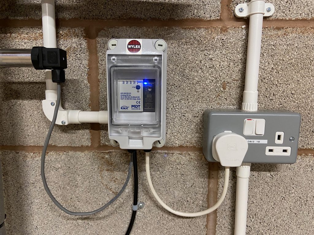
In the end, I settled on using the MDT KNX Analog Input-Output module, in its 4-channel DIN Rail Mounting variant (i.e. the MDT AIO-0410V.01) installed adjacent to a DIN Rail Mount 24V DC power supply from Mean Well (HDR-15-24, 15W 24V DC).
One reason for this decision is that the rainwater harvesting system is firmly part of the ‘fixtures and fittings’ rather than the ‘contents’ of the property, and in general I’m using KNX as the Home Automation ‘backbone’ for hard-wired ‘fixtures and fittings’ such as lights and window blinds. (Strictly speaking, since this is only for monitoring rather than being a ‘functional’ component of the rainwater harvesting system it doesn’t really need to be sold as part of the house, but never mind.)
Jumping ahead somewhat, the completed installation for the AIO module and 24V DC power supply is shown in the photo below. Note these are shared with the rainwater pipework pressure sensor (partially visible near the top-left of the photo). The black ‘wire’ connects to the pressure sensor submerged in the underground tank.
As-Implemented Solution
Physical Sensor
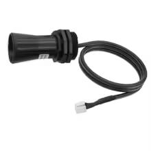
The hydrostatic pressure sensor was purchased for £34.14 from AliExpress, in mid-2025. While the listings there don’t always seem to persist for long, for now it’s showing as Submersible Water Level Sensor 4-20mA 0-10V RS485 Water Liquid Level Transmmitter 1m 2m 5m Level measuring instrument. That listing covers multiple variants but I bought the 2m range 10m cable Measuring Range with the 4-20mA ‘Color’ (meaning a 4-20mA electrical interface). While strictly speaking a 1m measuring range would have been just sufficient, that’s not available with a 10m cable – and the required cable run is around 8m (and – especially since the ‘cable’ includes a pressure tube – it’s difficult to extend (or shorten)).
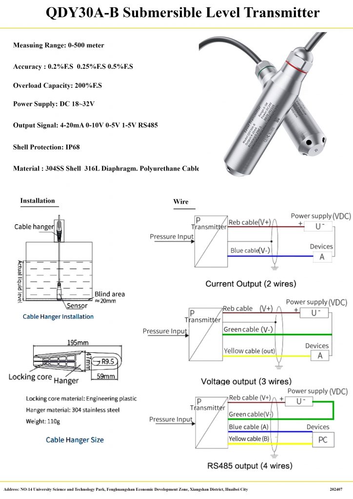
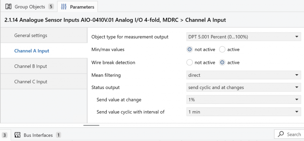
This sensor is wired to Input channel ‘A’ on the MDT AIO-0410V.01 (which coincidentally is acting as device ‘A’ in the “Current Output (2 wires)” wiring diagram).
KNX Configuration
The input is configured within the KNX ETS application as a 4 - 20mA Sensor type and there’s the option to convert the reading to various ‘environmental’ units – such as Temperature (C), Humidity (%) or Pressure (Pa). The option to report Volume in e.g. Litres isn’t offered – but that’s OK because the AIO device is not able to apply the complex conversion required to account for the shape of the tank anyway. The practical options are therefore:
- Leave the readings in Current (mA,) so they get reported ‘raw’
- Expected to be literally a value between 4 and 20mA
- Convert them to a Percentage of the 2m reading range of the sensor
- In other words, a value of 50 would be 50% of the 2m range, i.e. 1m of water depth
The option to report the value as a Percentage seems the most appropriate – since at least it masks the underlying 4 – 20mA technology, which isn’t relevant to any of the downstream processing.
A further consideration is whether the KNX AIO module should actively ‘publish’ updates for this reading or whether it needs to be ‘polled’ for the current value. Given that there is an option to have the reading ‘published’ when it changes (as well as periodically, when it doesn’t) that saves on having to configure ‘polling’ from Home Assistant – which is generally best avoided if possible.
Status output against the MDT AIO module within the KNX ETS applicationHome Assistant Configuration
With the MDT KNX AIO module reporting a Percentage value against a KNX Group Address, it’s straightforward to map that to a Home Assistant sensor type via a few lines of YAML in included configuration file knx.yml (assuming the KNX integration is already in place):
sensor:
  # RWH Tank Level Sensor
    - name: "RWH Tank Water Level (percent)"
      type: "percent"
      state_address: "5/5/1"
      state_class: "measurement"
      sync_state: "init"
The sync_state: "init" line says that Home Assistant should ‘poll’ once for the current sensor value when Home Assistant is initialising but then rely on the KNX module to ‘publish’ subsequent updates.
This results in a Home Assistant Entity which reports the Percentage value being published via the KNX Bus.
The next challenge is to apply a conversion factor to convert readings from Percentage values into a measurement of water depth2 – for which a Home Assistant Template Sensor is ideal. This is classed as a ‘Helper’ and so is created using Create helper, specifying:
Templateas the Helper typeSensoras the Template typeRWH Tank Water Level (mm)as the Name{{ states('sensor.rwh_tank_water_level_percent') | float * 20.0}}as the Statemmas the Unit of measurementDistanceas the Device classMeasurementas the State class{{ is_number(states('sensor.rwh_tank_water_level_percent')) }}as the Availability template (to ensure the State is being fed with a numeric value before attempting to convert it)
This results in a Home Assistant Helper which reports the depth of the water in the tank, in mm, that gets updated whenever the Percentage value changes.
Tank Volume Calculation
The tank is a rather odd shape – sort-of rectangular but with heavily rounded corners. Broadly speaking, it’s a set of 1m-diameter cylinders with quarter-spheres connecting the outer corners – with various additional strengthening webs etc.
My initial plan was to treat the four quarter-spheres at the corners as a single spherical tank and to treat the five sort-of-cylindrical sections as a horizontal, cylindrical tank. The stored-volume calculation for a horizontal cylindrical tank is published e.g. here and here. and for a spherical tank the ‘spherical cap’ formula is e.g. here.
A few experiments implementing those formulae with a standalone Python script were unable to reproduce the expected 5,000 litres of volume when the tank was full – which made me think that messing about with trigonometric functions is probably overkill. As a first-approximation, treating the tank as being a cuboid is probably ‘good enough’.
The water level sensor is showing 51% when the tank is full to overflowing (and quickly drops to 50% with even a tiny draw-off) so I’m going with the simplification that a 50% reading is 1m of water depth and equates to the full, nominal 5,000 litre capacity. That means that the depth in mm can be converted to a volume in litres by simply multiplying by 5. This will be inaccurate around the 3/4 and 1/4 full points but accurate at 1/2 full and not bad when it’s close to empty (and the mains top-up should kick in at around 250mm of water depth anyway).
There’s therefore a further Home Assistant Helper to convert the water depth to a simplified Stored volume measurement, created with:
Templateas the Helper typeSensoras the Template typeRWH Tank Water Volume (litres)as the Name{{ states('sensor.rwh_tank_water_level_mm') | float * 5.0 }}as the StateLas the Unit of measurementStored volumeas the Device class3Measurementas the State class{{ is_number(states('sensor.rwh_tank_water_level_mm')) }}as the Availability template (to ensure the State is being fed with a numeric value before attempting to convert it)
Next Steps
The tank is currently (February 2026) full to overflowing and in fact the water level is probably slightly entering the ‘neck’ of the tank so there’s little scope for calibration of the calculations right now. The plan is to check the reported water level against the measured water level during the summer, as the tank empties, and also check how the reported stored volume compares with the recorded rainwater usage from the water meters (during a dry spell).
It will also be interesting to see at what water level the mains top-up kicks in – which should be the minimum water level that gets reported.
A possible further enhancement would be to add a prediction of the number of days of stored rainwater remaining, based on the stored volume and the recent (past 24 hours?) rainwater consumption.
Water Pressure Sensor
Physical Sensor
There are few technology options available for pipework pressure sensors. The sensor was purchased for £21.64 via AliExpress in mid-2025. While the listings there don’t always seem to persist for long, for now it’s showing as G1/2 pressure transmitter sensor 0-1bar 3bar 0.5bar 150bar DC24V DC5V pressure transducer hydraulic 4-20mA 0-10V 0.5-4.5V 0-3.3V. That listing covers multiple variants but I bought the 0-10bar Measuring Range with the 4-20mA G1-2 ‘Color’ (meaning a 4-20mA electrical interface and a G1/2 (i.e. 1/2″ BSP) threaded pipe fitting). The rainwater pump is rated for 6 bar so the next-lowest 0-5bar range might have maxed-out.
This particular unit is not pre-wired so it’s necessary to consult the instructions to check the cable connections for 4-20mA operation – which is basically +24V to Terminal #1 and 0V to Terminal #2, with the current-measuring ‘Instrument’ and 24V DC power supply wired in series.
This sensor is wired to Input channel ‘B’ on the MDT AIO-0410V.01 (which is acting as the measuring ‘Instrument’ shown in the wiring diagram).
KNX Configuration
The MDT AIO modules are highly configurable, with each ‘channel’ able to operate as either an Input or an Output. An Output is always Voltage-based but an Input can be Voltage-based (either 0-10V or 2-10V) or Current-based (either 0-20mA or 4-20mA).4 With a 4-20mA Input selected, there are further options for how the reading should be presented as a KNX object type.
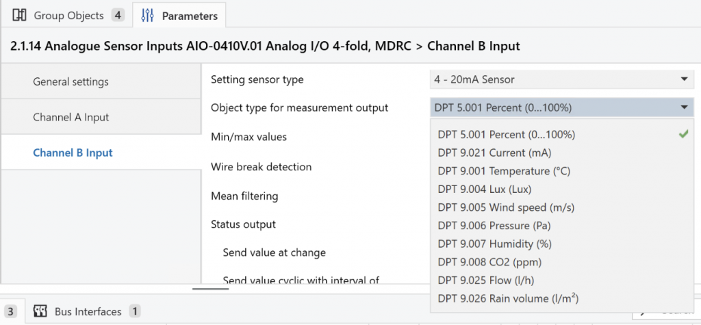
Object type for measurement output against the MDT AIO module within the KNX ETS applicationGiven that DPT 9.006 Pressure (Pa) is one of the available options it seems tempting to select that – but there’s a catch. If that option is selected further fields appear for the entry of ‘Scaling’ factors – effectively specifying what Pascal pressure values 4mA and 20mA readings equate to.
The catch is that for this 0-10 bar sensor, 20mA equates to 10 bar, which is 1,000,000 (1 million) Pascals – and that’s greater than the maximum scaling factor of 670,000 Pascals (6.7 bar) permitted by the MDT KNX AIO module.5
Initially I was inclined to enter a scaling factor of 100,000 instead, meaning that the sensor would report up to 100,000 Pa (i.e. 1 bar) and meaning that somewhere down the line it would be necessary to remember to multiply that by 10 to correct it. On reflection that seems like a bad idea – because it looks like a correct pressure reading when it isn’t. So instead it’s being reported as a Percentage, which forces a (correct) conversion to happen elsewhere (i.e. in Home Assistant – which can also then use bars rather than Pascals, for convenience).
There’s a basic pressure gauge incorporated within the rainwater pump controller that allows a crude check of the accuracy of the pressure sensor. When the sensor is reporting 36% the gauge reads 3.5 bars, which I decided was probably a 0.1 bar error in the gauge. (After drawing off a couple of litres, the sensor was reporting 31% with the gauge showing 3.0 bars.)
Home Assistant Configuration
With the MDT KNX AIO module reporting a Percentage value against a KNX Group Address, it’s straightforward to map that to a Home Assistant sensor type via a few lines of YAML in included configuration file knx.yml:
  sensor:
    # RWH Pump Pressure Sensor
    - name: "RWH Pump Pressure (percent)"
      type: "percent"
      state_address: "5/5/3"
      state_class: "measurement"
      sync_state: "init"
The sync_state: "init" line says that Home Assistant should ‘poll’ for the current sensor value when Home Assistant is initialising but then rely on the KNX module to ‘publish’ subsequent updates.
The next challenge is to apply a conversion factor to convert readings from Percentage values into bar values – for which a Home Assistant Template Sensor is ideal. This is classed as a ‘Helper’ and so is created using Create helper, specifying:
Templateas the Helper typeSensoras the Template typeRWH Pump Pressure (bar)as the Name{{ states('sensor.rwh_pump_pressure_percent') | float / 10.0 }}as the Statebaras the Unit of measurementPressureas the Device classMeasurementas the State class{{ is_number(states('sensor.rwh_pump_pressure_percent')) }}as the Availability template (to ensure the State is being fed with a numeric value before attempting to convert it)
In summary, there’s a Home Assistant Entity which is tracking the raw percentage reading from the KNX bus, which gets converted by a Home Assistant Helper into a proper pressure reading, in bar, for display on Dashboards etc.
- The rainwater consumption is measured by M-Bus-connected water meters – one inside the House and one in the Outbuildings ↩︎
- Since calculating the Volume of water stored in the tank is the ultimate goal it would be straightforward to calculate that directly – but I wanted an ‘intermediate’ value which can be verified using a tape measure ↩︎
- Note:
Stored volumeand not simplyVolume– since the latter is treated as a ‘fixed’ orTotalvalue (for something like the size of a room) whereas the former is aMeasurement↩︎ - The 2-10V and 4-20mA operating modes allow for detection of cable breakage or power supply failure and so are more robust in operation than when 0 Volts or Amps is a legitimate reading. ↩︎
- Looking at the other options for units, they all seem to relate to ‘environmental’ parameters so presumably the Pressure reading is intended for use with an atmospheric pressure of around 1 bar. ↩︎
![]() Rainwater Harvesting System Monitoring by Marsh Flatts Farm Self Build Diary is licensed under a Creative Commons Attribution-ShareAlike 4.0 International License.
Rainwater Harvesting System Monitoring by Marsh Flatts Farm Self Build Diary is licensed under a Creative Commons Attribution-ShareAlike 4.0 International License.