
The Outbuildings are getting a ‘light-touch’ Home Automation solution – compared with the House – which has dimmable LED lights connected to DALI-controlled dimmable drivers. None of the lights need to be dimmable so they’re all wired back to KNX-controlled 230V relay banks. (As it happens, some of the light fittings will be Philips SceneSwitch enabled, providing the option to dim them in 3 stages by switching on-and-off quickly – and then they remember the setting for next time.)
The question then is how to control these lighting relays:
- The small rooms (Plant Room and Shower Room) suit automated presence detection, with PIR sensors connected directly to the KNX bus
- All of the lights will be individually controllable via a Smartphone app (e.g. Home Assistant)
- There’s plenty of scope for using inputs from the garage door openers, CCTV cameras or the alarm system to automatically switch lights on and off
- For example, all of the external doors will have alarm sensors and these could be configured to switch on the lights in the relevant room (even if the alarm isn’t ‘armed’)
- It’s still sensible to provide a wall-mounted light switch in most rooms, so the lights can be turned on and off near the entrance doors.
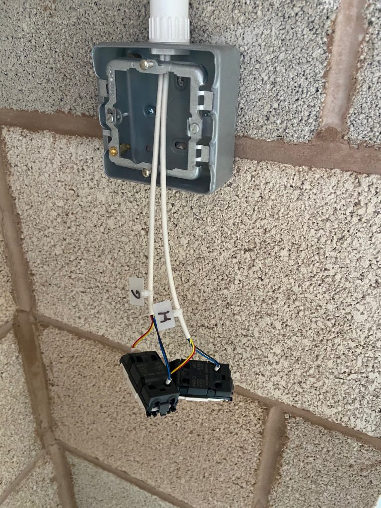
As with some of the rooms in the House, the ‘light switches’ are momentary-action switches wired to a low-voltage ‘binary input’ sensor bank – an MDT BE16000 that used to be in the House but was replaced by a smaller unit, specifically to free up the 16-channel unit for the Outbuildings. The ‘binary input’ module sends 12V down one of the wires then constantly watches for this appearing on the monitored inputs. For such a low voltage the cabling doesn’t need to be highly insulated (or to carry a high current) – but there are some long runs (up to 50m) so a fairly low resistance is preferable. I opted to use 4-core ‘alarm’ cable, being careful to choose Copper (rather than Copper Coated Aluminium) conductors1. Each of the 4 cores is 0.22mm2 stranded cable and since only two cores are required these are doubled-up. I always use crimped ferrule ends when terminating any stranded cable and two 0.22mm2 cores fit nicely into a 0.5mm2 ferrule. The ’12V’ connections at the Binary Input module are shared between two monitored channels so these have four 0.22mm2 cores in a 0.75mm2 ferrule.
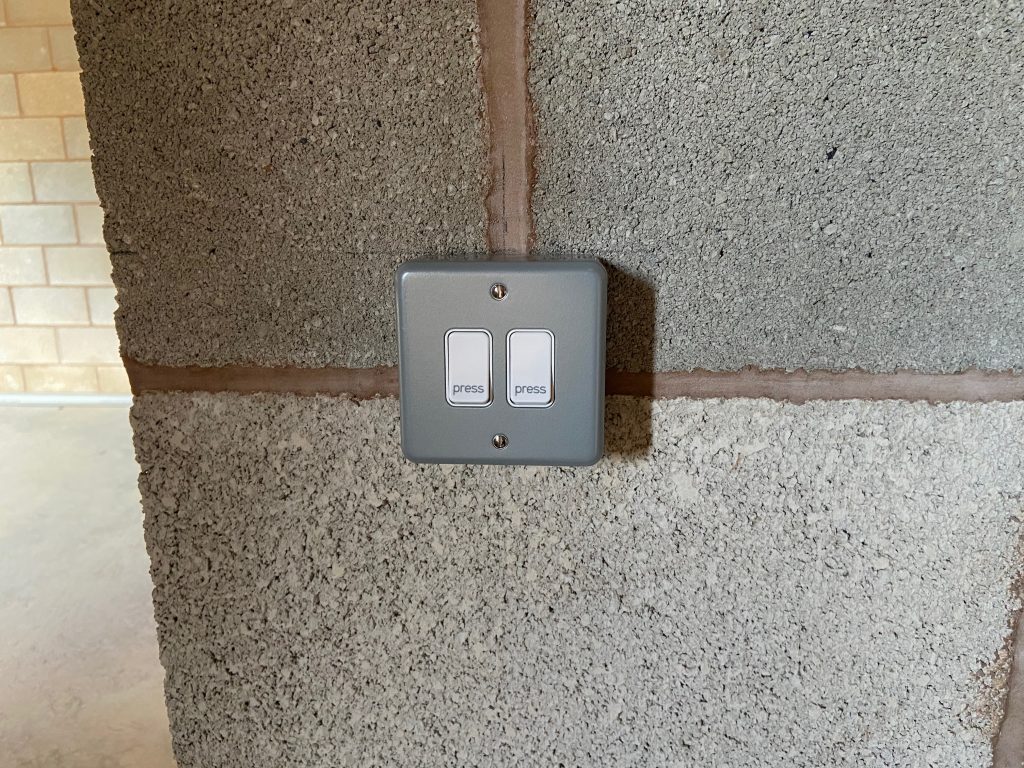
The switches themselves are MK Retractive Grid Module Switches (K4885P WHI) which fit into the MK Grid System frames and Metalclad Plus surface-mount boxes. Some reviews for these switches complain they’re incredibly hard to press, but I’ve not found that to be the case at all: they’re the same as the Logic Plus (white plastic faceplate) switches in the House.

Since the ‘alarm’ cable isn’t rated for mains voltage it can’t share conduit with 230V cabling so is installed in its own conduit – though in some cases this is shared with the cabling for the alarm system.
- The House used ‘KNX’ cable for this purpose – specifically to allow the selective upgrading of these momentary-action ‘dumb’ switches to fully-fledged KNX switches, which has been done for 6 of the switches in the House – which is why the 16-channel Binary Input module in the House could be downgraded to an 8-channel unit. KNX cable is a lot more expensive than ‘alarm’ cable though – and should never be required for the Outbuildings. (If any of the switches does need swapping for a ‘native’ KNX switch in the future, it would be easy enough to pull a KNX cable into the conduit.) ↩︎
![]() Outbuildings – Home Automation – Light Switches by Marsh Flatts Farm Self Build Diary is licensed under a Creative Commons Attribution-ShareAlike 4.0 International License.
Outbuildings – Home Automation – Light Switches by Marsh Flatts Farm Self Build Diary is licensed under a Creative Commons Attribution-ShareAlike 4.0 International License.