No contractors on-site today: the flooring team are leaving the self-levelling floor screed a bit longer to fully dry – though there’s some news on the availability of the replacement concrete headwall for the stormwater attenuation pond, which is due for delivery on Friday, so work is planned to start up again tomorrow.
In the meantime I’ve been progressing the rigid MVHR ductwork that was cut and dry-fitted recently. All the joints were sealed with the supplied (Soudaduct) duct sealant and then taped with the supplied aluminium tape. The sealant stays permanently flexible so isn’t a structural adhesive whereas the wide aluminium tape does add significant structural integrity – as well as being belt-and-braces for air tightness.
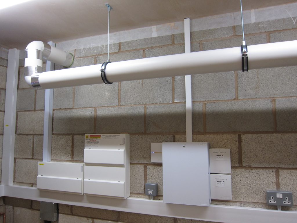
The long run of Intake duct, with sealed and taped jointsThe rest of the MVHR rigid ductwork, with all joints sealed and taped
I’m going to commission the MVHR system before adding the insulation to the two ‘external’ ducts, which should be easy enough on the long straight runs but could be challenging on the bends.
I decided to install the MVHR system myself, since most builders still don’t seem very familiar with the technology and while some aspects are a bit fiddly none of the work is difficult. As the building is not considered a “Dwelling”, Building Control aren’t concerned about the certification of the ventilation installation – whereas they would be in a House.
Overall I’ve been pretty happy with the MVHR installation ancillaries supplied by BPC Ventilation to complement the Vent-Axia MVHR unit, but there was nothing specific included in the kit to support the 125mm diameter rigid(-ish) ventilation ducts. There was a reel of ‘builders band’ included in the kit which worked well to strap down the small diameter semi-rigid ducts above the ceiling but there wasn’t much of that left – and I don’t consider it a good solution for the larger diameter rigid ducts anyway.
Some suppliers want a lot of money for duct support brackets but Direct Channel Support Systems, who I used for the cable baskets, offer a nice range of pipe / duct support brackets at very reasonable prices. 5 of the 125mm duct brackets, 4 support brackets and a 2m length of M8 threaded rod were only £10.35.
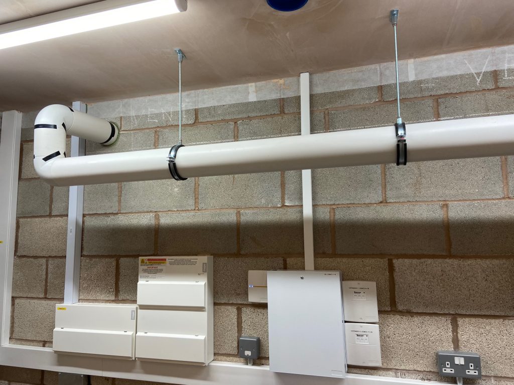
Two of the duct support brackets securely holding the long run of horizontal duct
The range of brackets from Direct Channel includes ‘double’ brackets which allow one duct to be supported directly above another one, which must be quite a common requirement.
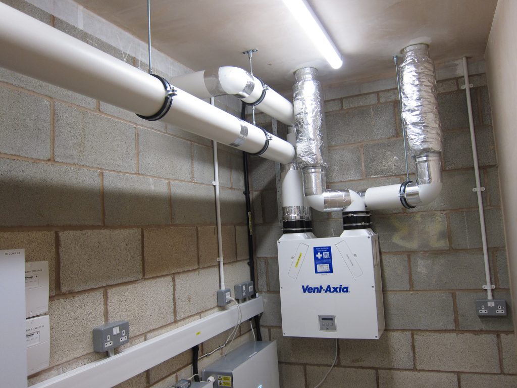
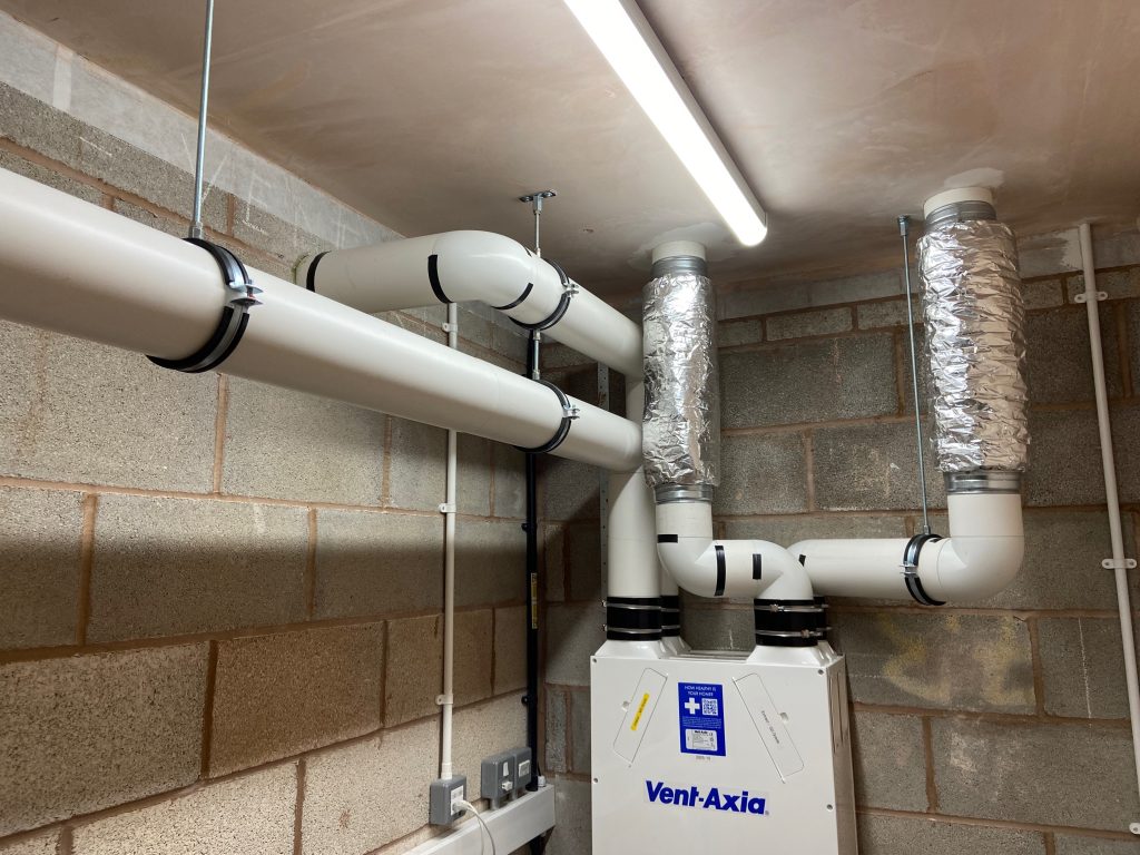
Wider shot of the MVHR unit and ductwork, showing a ‘Double’ bracket mounted directly above a ‘Single’ bracket for the external ducts. The ‘tinfoil’ sections are silencers covered with foil-backed fibreglass insulation, which help to stop fan noise propagating to the room vents.
Temporarily, there’s just black insulation tape holding the lengths of ducting to their fittings but now all of the rigid ducting has been dry-fitted that needs to be replaced with duct sealant and aluminium tape (both supplied in the BPC kit).
Once all the duct joints have been sealed, the two ‘outdoor’ ducts need insulating (foil-backed fibreglass insulation was also supplied in the kit) since they will both be carrying air at ‘outdoor’ temperatures through a heated space, making them prone to condensation – as well as heat loss.