There is no mains drainage available at the site so the plan has always been to use a small sewage treatment plant for the new house and to install this early so it can also be used by the static caravan during construction. The old house had a traditional brick septic tank, discharging into the field drainage ditch, but this was well past its best and those old designs simply cannot match the treatment quality of modern systems.
Some time ago I settled on using a Biorock system. These are one of a handful of designs that don’t require an electricity supply: most other systems rely on either an aeration pump or rotating discs to treat the effluent whereas the Biorock system relies on natural ventilation of a treatment unit with aerobic bacteria hosted on a stack of foam cubes contained in string bags. While a Biorock unit is more expensive than the alternatives the zero electricity cost offsets the higher purchase price relatively quickly and the sheer simplicity of the system is very appealing.
Upstream of the main Biorock treatment unit there’s a separate, large settlement tank divided into two sub-chambers with a brush filter on the outlet which keeps solid matter out of the Biorock unit itself. Downstream of the Biorock there’s a small vertical access shaft for sampling the final discharge quality or, if necessary, for installing a pump to raise the treated effluent to a higher level. One characteristic of the Biorock system is that the main treatment chamber is relatively dry, holding just a shallow layer of water at the bottom, and as a result the outlet is 1.15m below the inlet and the outlet must be allowed to drain freely. On a flat site this means a pump is often required whereas on a sloping site it can be possible to do everything by gravity. On my site it proved just possible to arrange for a gravity outfall to the same drainage ditch used by the old septic tank, though some of the pipe runs are at the minimum permitted gradient (1:200 for treated effluent) and the Biorock unit needed to be located with the top roughly 0.8m above the current ground level in its immediate vicinity. The ground level will be raised later as part of the site landscaping scheme.
With the Biorock being relatively unusual in the UK (my architects, my structural engineer and my building control inspector had not come across one before) there aren’t that many installers who are experienced in the specific requirements and I wanted to ensure the installation was done correctly. Biorock UK recommended Mike Welton of Welton Environmental and Mike did a great job, installing the tanks and about 50m of inlet and outlet pipework in 3 days with just the help of a good local JCB and operator.
Different sizes of Biorock units are available to cater for different sizes of dwelling, based on the “Population Equivalent” (PE) definitions of e.g. the British Water standards. The smallest 5 PE unit is suitable for a 3-bedroom house, but since my house will have more bedrooms than that I needed the next size up, the 10 PE, which is good for up to 8 bedrooms. This is paired with a 3,300 litre primary tank, and then although I don’t (currently) need to pump the outlet it seemed like good insurance to install the 400mm diameter “pump shaft” rather than the 160mm diameter “sampling tube” just in case a pump is required to help the flow along at a later date.
With the tanks raised out of the ground more than would be normal on most sites they didn’t require too deep a hole and the ground conditions were good.
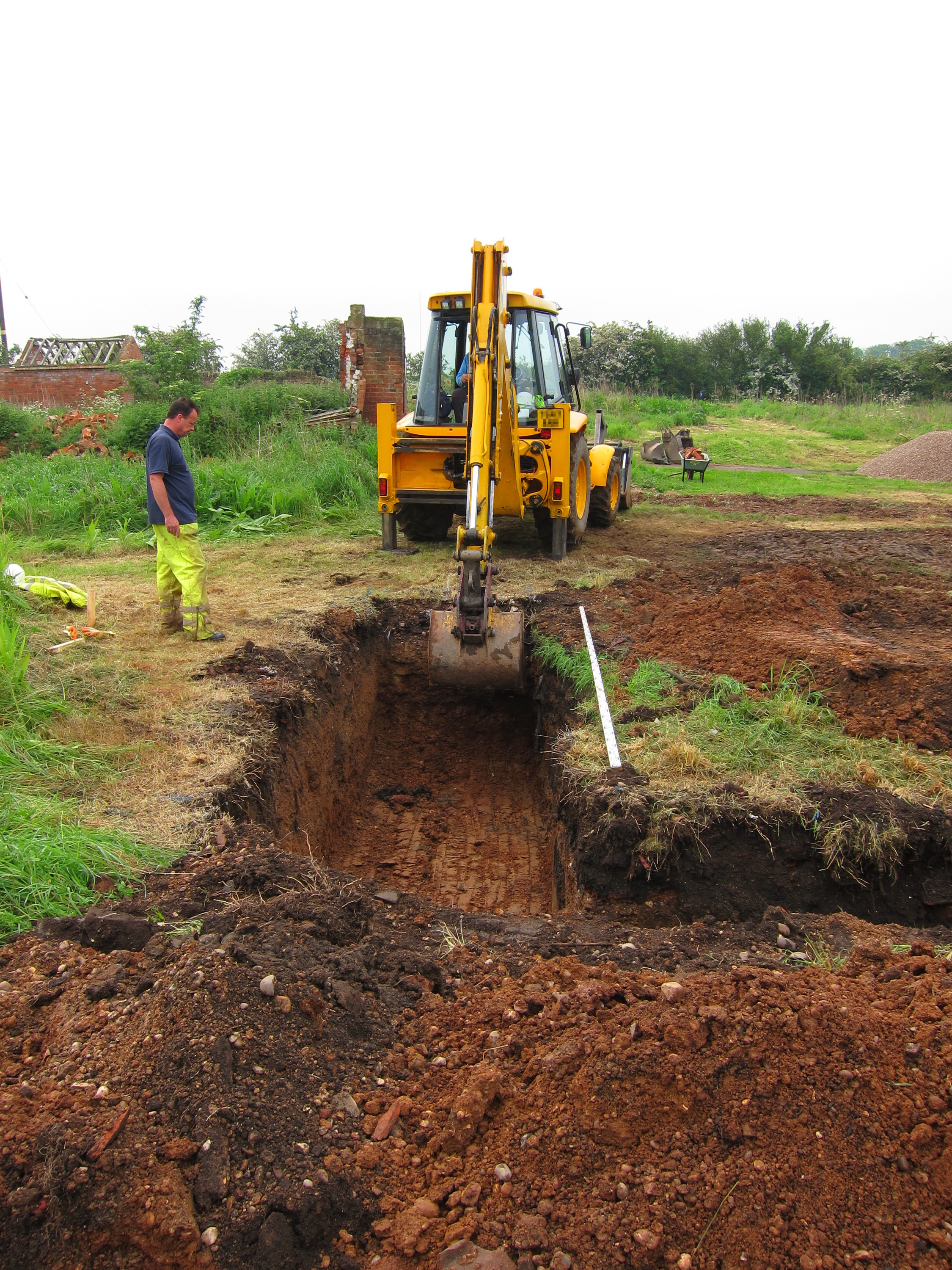
Digging the hole for the tanks
Due to a couple of hiccups with deliveries (the first primary tank had a hole in it but Biorock UK managed to ship a replacement overnight, and then the concrete plant sent a regular wet mix rather than the requested dry mix which took 3 hours to correct) I wasn’t able to be present for the actual installation but I took photos once I got back from work.
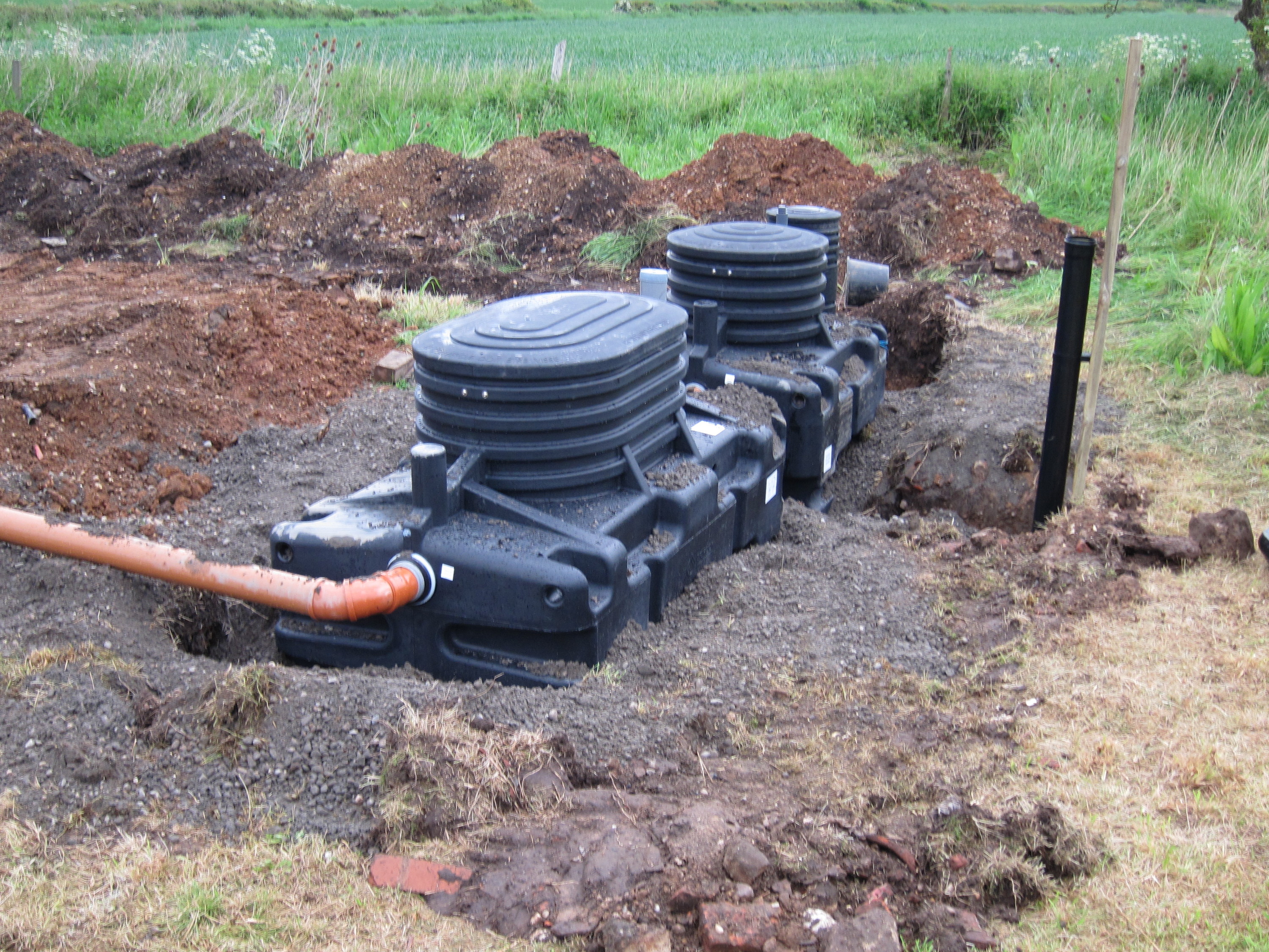
The primary tank (foreground) and the Biorock tank with dry-mix concrete back-fill.
The inlet pipe (left of shot) is just temporary to permit the tanks to be partially filled to balance the pressure of the back-fill.
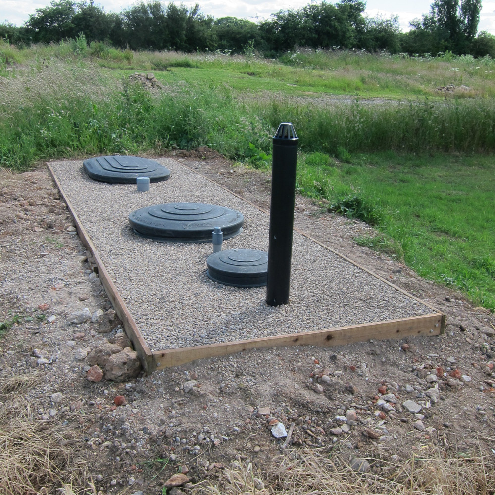
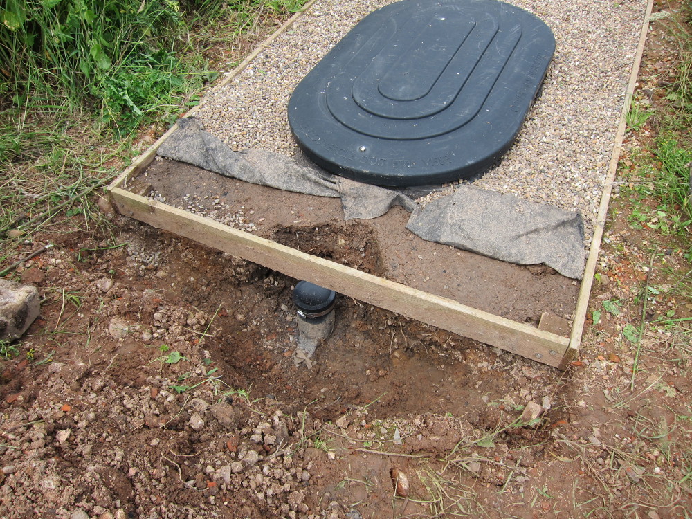
Once covered with soil up to what will become the new ground level the tanks look less prominent. From left to right, the visible features are:
- The air intake pipe (110mm diameter, black, approx 600mm high)
- The cover for the 400mm diameter pump shaft / sample chamber
- The alarm rod (40mm, grey; connected to a float to indicate if the water level rises too high within the Biorock unit)
- The cover for the Biorock unit
- The temporary ventilation pipe for the Biorock unit (110mm diameter, black; rises to approx 4m, out of shot)
- Once the barn is re-built this will be relocated and attached to the side of the barn but for now it makes sense to keep it well out of the way of the demolition and construction work
- The cover for the brush filter on the outlet from the primary tank (110mm diameter, grey)
- The cover for the primary tank
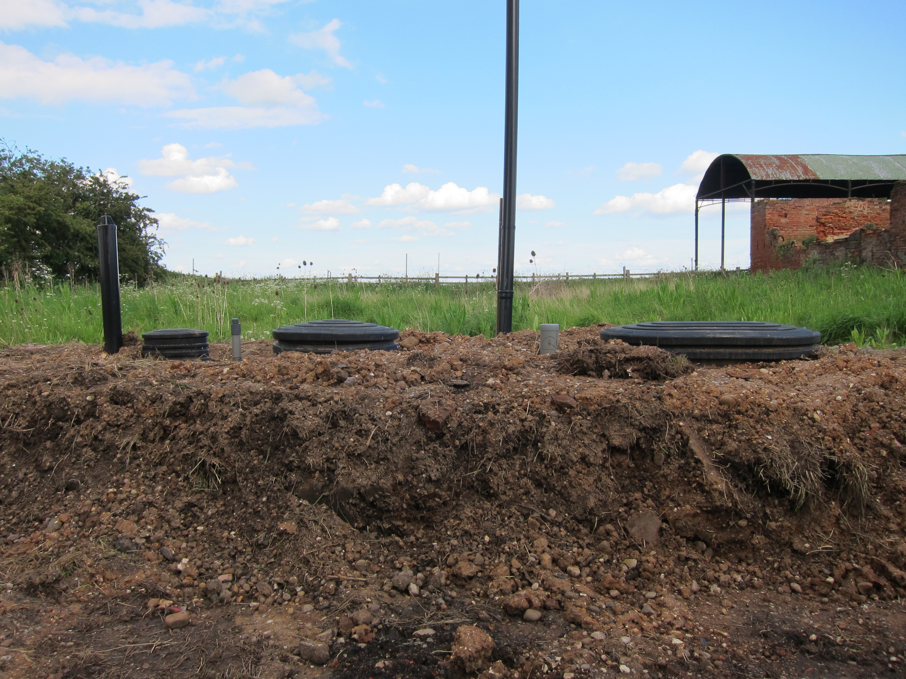
The installed tanks and associated vent pipes
There’s nothing much to see within the primary tank (it’s just a tank, with a baffle about 2/3 of the way along) but the Biorock unit is a little more interesting. Mike tells me the foam cubes come impregnated with a bacteria culture to kick-start the treatment process once they get wet.
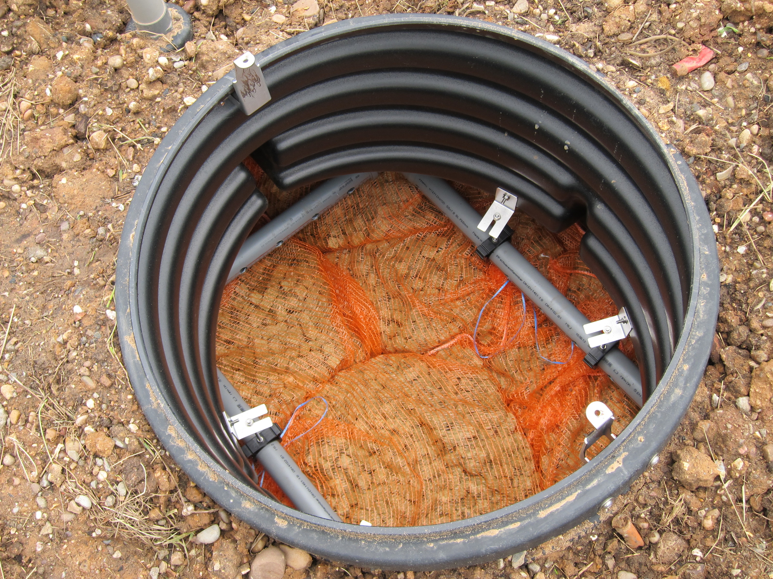
The view in the top of the Biorock unit, showing the grey effluent delivery pipes and the foam media inside orange string bags
While sewage treatment might not be the most exciting aspect of the new house this installation marks a milestone as being the first part of the permanent construction to be completed and so it feels like a pretty big deal.
Update 2015-06-28
After just over a year, the Biorock system is still working perfectly. The soil around the tanks had grown lots of weeds so, since this is a permanent installation and part of the future garden, I decided it would be better to lay some gravel to stop the weeds and tidy up the area. While that’s not quite as simple as it sounds – the gravel needs some sort of enclosure and there needs to be a layer of landscape fabric to stop the weeds growing through the gravel – the finished result looks good. I also secured the bottom of the vent stack in concrete to stop it moving.
Gravel around Biorock tanks
Update 2016-07-03
Another year on and the system has been working perfectly – up until recently. The new house has been under construction since October 2015 with a small core team on-site every day and various subcontractors coming and going at other times. Somewhere down the line one of the subcontractors evidently thought it was acceptable to flush kitchen towels down the site toilets. This would be asking a lot of mains drainage and was never going to turn out well with a system like the Biorock. The brush filter on the outlet from the Primary tank stops anything getting into the Biorock unit itself but it’s still possible to get a blockage at the inlet to the Primary tank.
The problem showed up as a raised water level in the manhole leading to the primary tank. Rodding it helped temporarily and definitely moved water into the primary tank but the level in the manhole didn’t drop. It took a while to work out what was happening and there’s not much to see from inside the Primary tank – just a translucent white box around the inlet – so the cross-sectional sketch below should help to make things clear.
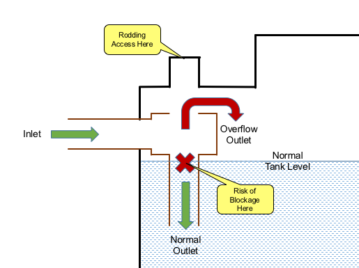
Biorock Primary Tank – Risk of Blockage and Rodding Access
Under normal circumstances the sewage flows in from the left and then drops into the vertical tube. Generally that works fine and everything clears down the tube but there’s a risk of a blockage forming near the top of the vertical tube. If that happens there’s an overflow out of the top of the white plastic box, but that’s roughly 150mm above the normal tank level – hence the raised level in the upstream manhole.
The only way to clear such a blockage is to come in from the top of the tank and rod down the vertical tube. There’s an access point (possible air vent location?) moulded into the top of the tank which is directly above the vertical tube (I wasn’t completely certain that would be the case, but it is) and for my installation that was still closed off and I had to cut the top off with a hacksaw.
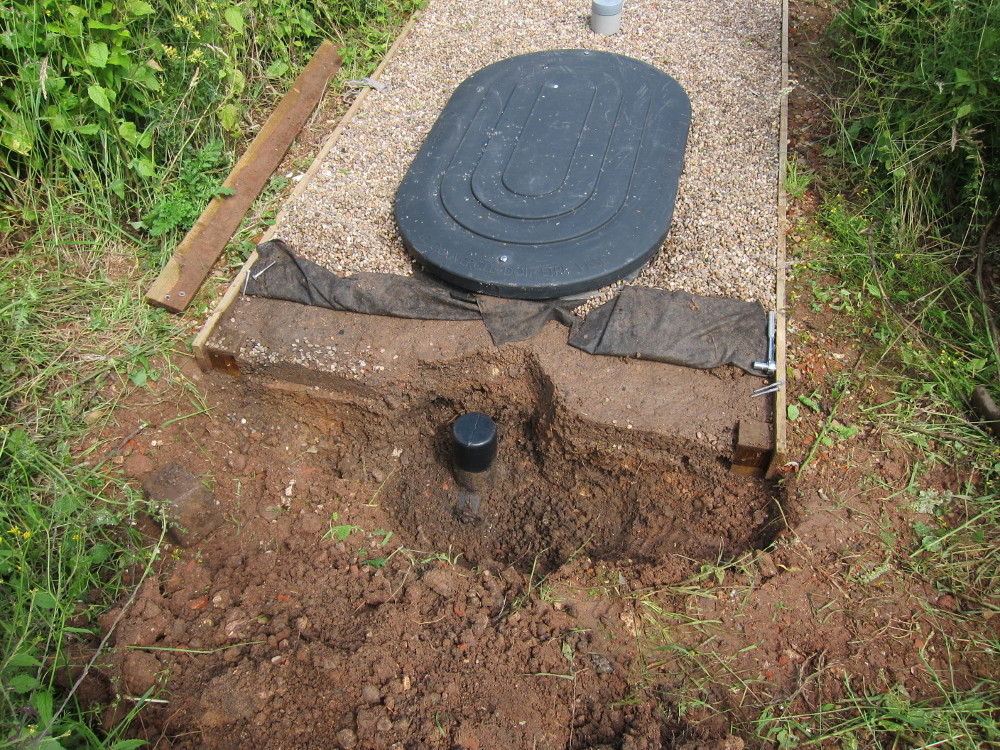
Moulded rodding access at inlet end of Primary tank, excavated and wiped clean
Not predicting the need to gain such access I’d foolishly located the end gravel board directly over the centre of the access port! My Plan A was to permanently fit a screwed rodding point at ground level but I can’t face re-working the gravel boards right now so I just fitted a flexible rubber end cap and put the gravel board back over it. The “pipe” is nominally 110mm diameter but it is moulded in thick polythene and not as accurate as an extruded PVC pipe would be, so a flexible coupling secured with a stainless steel Jubilee clip is a good way to go.
Cover cap fitted and gravel board replaced
Judging by the drawing of the latest specification of BIOROCK-ST1-3000 Primary tank from the Biorock website (PDF link here) it looks like it might now be standard practice to fit an accessible rodding point in this location. I’d definitely recommend doing that on any new installation.
Despite this minor setback which was directly attributable to misuse of the system it’s working very well and I continue to thoroughly recommend the Biorock products. The quality of the treated discharge remains excellent.
Update 2020-08-01
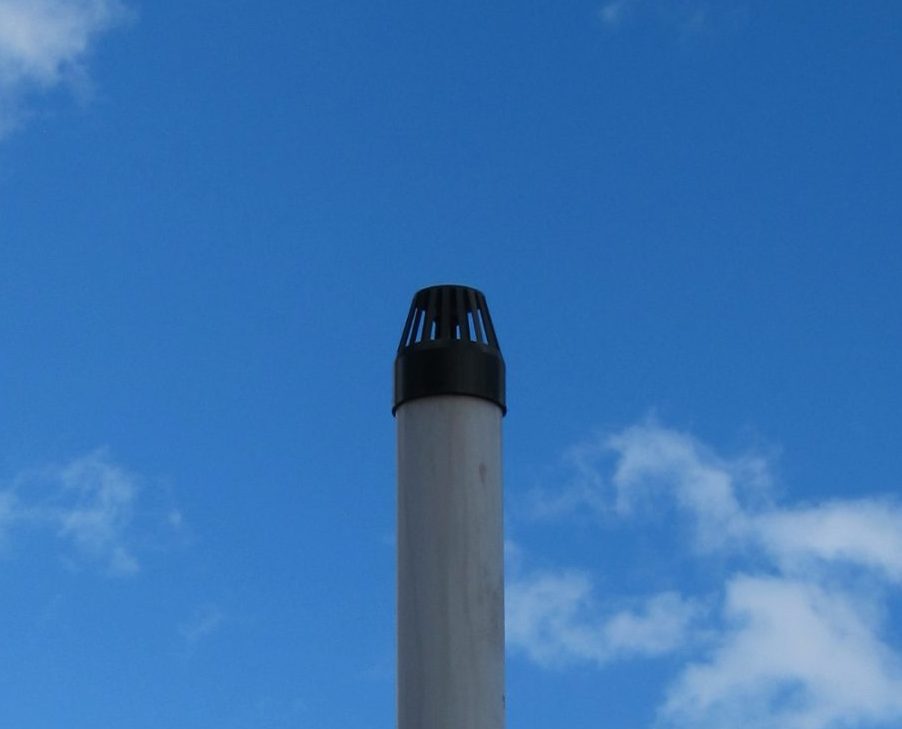
When originally installed the two ventilation stacks for the Biorock tanks were fitted with simple grilles to keep birds and debris out. While working on the dressing room which has one of several Air Admittance Valves for the drainage system I noticed that in some wind conditions the drains were being pressurised relative to the house and the AAVs were lifting slightly and venting the drains into the house.
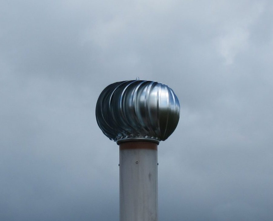
The fix for this was to fit a wind-driven rotating cowl to the ventilation stack on the primary tank, which also vents the house drains. Some of these cowls can be reasonably expensive but I found a 100mm unit for £39.99 from fans4less.co.uk which seemed like it was worth a try. It’s early days but the results seem pretty good and I’m now going to fit a matching cowl to the vent for the secondary tank too.
  |
Looking again at the Biorock website, there seems to be a stronger recommendation than I remember to fit these sort of wind-driven cowls as a matter of course and they have a new Wind-Driven Ventilator (PDF data sheet here) which looks nicely engineered (and only suitable for ventilation since it’s made of plastic) but it’s €150. Both my vent stacks are only temporary-ish (they’ll be mounted on the re-built barn whenever that gets constructed) so I’ll review whether to swap to the Biorock ventilators when that happens, depending on how the bearings on the cheaper models hold up.
Update 2023-11-01
Three years on and the cheap wind-driven ventilator has seized up. I removed it to check if the bearings could be replaced and found it was all very badly rusted – surprisingly more so on the sleeve that fits inside the pipe than on the blades themselves. On reflection, a coat of spray paint might have helped.
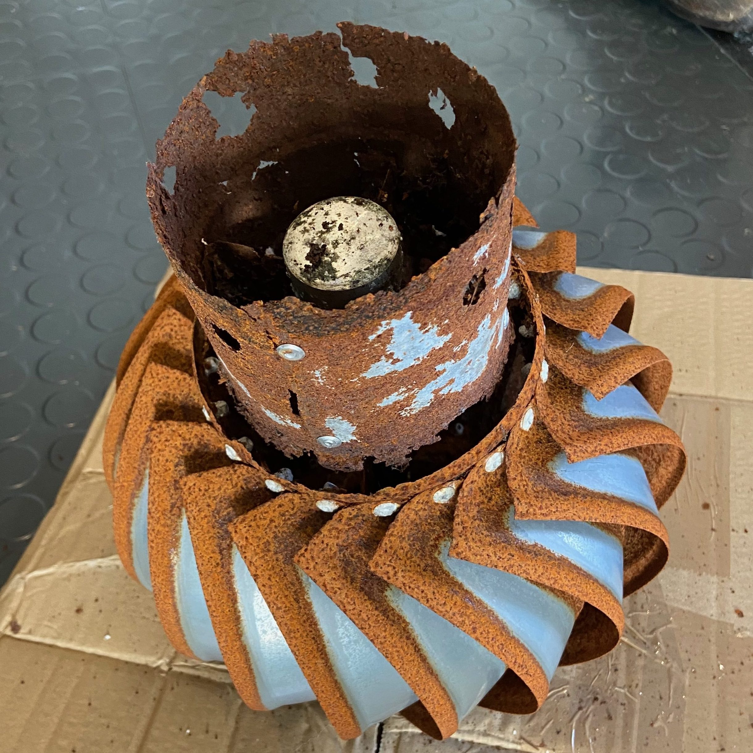
Researching for replacements, my preference is now for the Biolan Wind Fan which is specifically designed for ventilation use-cases. It’s made of aluminium so should resist corrosion – plus it’s painted black. Judging from the instruction manual, the bearings seem more accessible and maintainable, and it will always tend to be the bearings that limit the life of these units.