Thermographic Survey of Air Leakage

The air tightness of the building is still falling short of the Passivhaus requirement of 0.6 Air Changes per Hour at 50 Pascals of pressure – the last test came in at around 0.9. Clearly that means there’s more air leakage than there should be but the problem has been in locating where the leakage is happening in order to fix it.

The architect, the contractor and myself all made enquiries and it became evident that the most practical approach was to do a thermographic (i.e. thermal camera) survey following the procedure defined in “BS EN 13187:1999 Thermal performance of buildings – Qualitative detection of thermal irregularities in building envelopes – Infrared method”.

The main challenge with this procedure is that it relies on a significant temperature difference between the inside and the outside of the building (at least 10 degrees and ideally more) in order to show where air leakage is either heating or cooling the surfaces. Since the air tight barrier is on the inside, the basic approach is to:

  • Heat the inside of the building to a consistent temperature of more than 20 degrees
  • Use a blower door to de-pressurise the inside of the building so that external air is drawn in through the air leaks
  • Use a thermal camera to check for cold spots caused by the outside air causing cooling around the air tight barrier

For this to work best, the outside air wants to be as cold as possible – which also means the external surfaces must not be heated by the sun. The ideal time to do the test is therefore in winter (when the outside air is cold) and before dawn (when all of the external surfaces have cooled down overnight and not yet received any sunlight). The perfect time of year is around the end of December, when dawn is relatively late and the outside temperature is generally cold.

The equipment and skills required are quite specialised and only a few consultants offer this service. I contacted Apex Acoustics (largely on the basis of them having a Midlands office in Nottingham) who provide air tightness consultancy alongside acoustic consultancy. It turned out their thermographic expert is Mark Siddall (well known in the UK Passivhaus community) who is based near the Apex Acoustics main office in Gateshead.

The survey was completed this morning and showed a significant leak in a store room above the balcony and a few minor leaks elsewhere. I’ll update this post with some of the thermal camera photos when I get them from Mark.

The plan is now to fix the leak above the balcony and to check what that does to the overall air tightness figure, with the hope that it will be enough to enable Passivhaus certification.

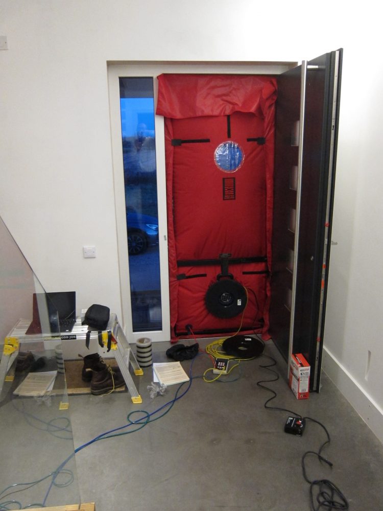
Blower door doing its thing during Thermographic Survey

Electric Nation Electric Car Charger Installed

As reported previously, my application to join the Electric Nation research trial was accepted a few weeks ago. The eVolt EVSE unit was installed today.

A few of the reports from the Electric Nation project are being published on the Western Power Distribution website, for example this one about Algorithm Development and Testing.

eVolt EVSE unit installed outside

The outdoor eVolt unit has a high capacity 230V mains connection and a wired Ethernet network connection. The two cables run alongside each other which can cause electrical interference but the installer assured me the outdoor-grade Ethernet cable would cope with this – I presume it includes a foil shield.

In addition to the EVSE unit itself (outside) three smaller units were installed inside:

  • A small distribution board containing a 63A 30mA RCD, a 40A MCB for the eVolt unit and a 6A MCB for the power supply to the comms units (top-centre in the photo below, labelled DB/1B)
    • While the EVSE is rated for up to 32A, I’ve heard elsewhere that no MCB likes running at its full rated capacity for long periods so it’s correct for the MCB to be rated a bit higher
  • A CrowdCharge device which provides some of the remote control functionality for the trial (bottom-right in the photo below)
    • I haven’t studied this in detail but the box contains two boards, one of which seems to be a multi-port Router (it has a MikroTik MAC address) and the other is presumably some sort of single-board-computer
    • Each board takes a 5V USB power supply, hence the two USB leads
  • A hard-wired twin-socket USB power supply (with its own fused spur) for the CrowdCharge device (bottom-left in the photo below)

Electrical supply and communications units inside

I already had a spare Ethernet network socket near the distribution boards to provide a hard-wired connection for the CrowdCharge device; if that was not available they would have installed a WiFi Bridge unit as well.

I’m well aware that the electrical installation at Marsh Flatts Farm is somewhat more complex than you’d find in a standard house so I was very careful to explain exactly what it consists of in the self-survey response. Despite my best efforts the engineers at the installation company had missed the fact there are 4 distribution boards (consumer units) in total and the installer was concerned about not having 32A of headroom from the 80A supply so the EVSE has initially been capped at 16A.

The installation company is going to send me an OWL monitor so they can check how much of the 80A I’m normally using. My own monitoring shows there’s never less than 40A spare so that should be a formality. Once they’re happy, the EVSE will be remotely re-configured to supply up to 32A as originally intended.