Multi-Target KNX Home Automation Configurations

Generally speaking I get on very well with the KNX Home Automation standard and the ETS software used to configure a KNX installation, but every now and again it catches me out.

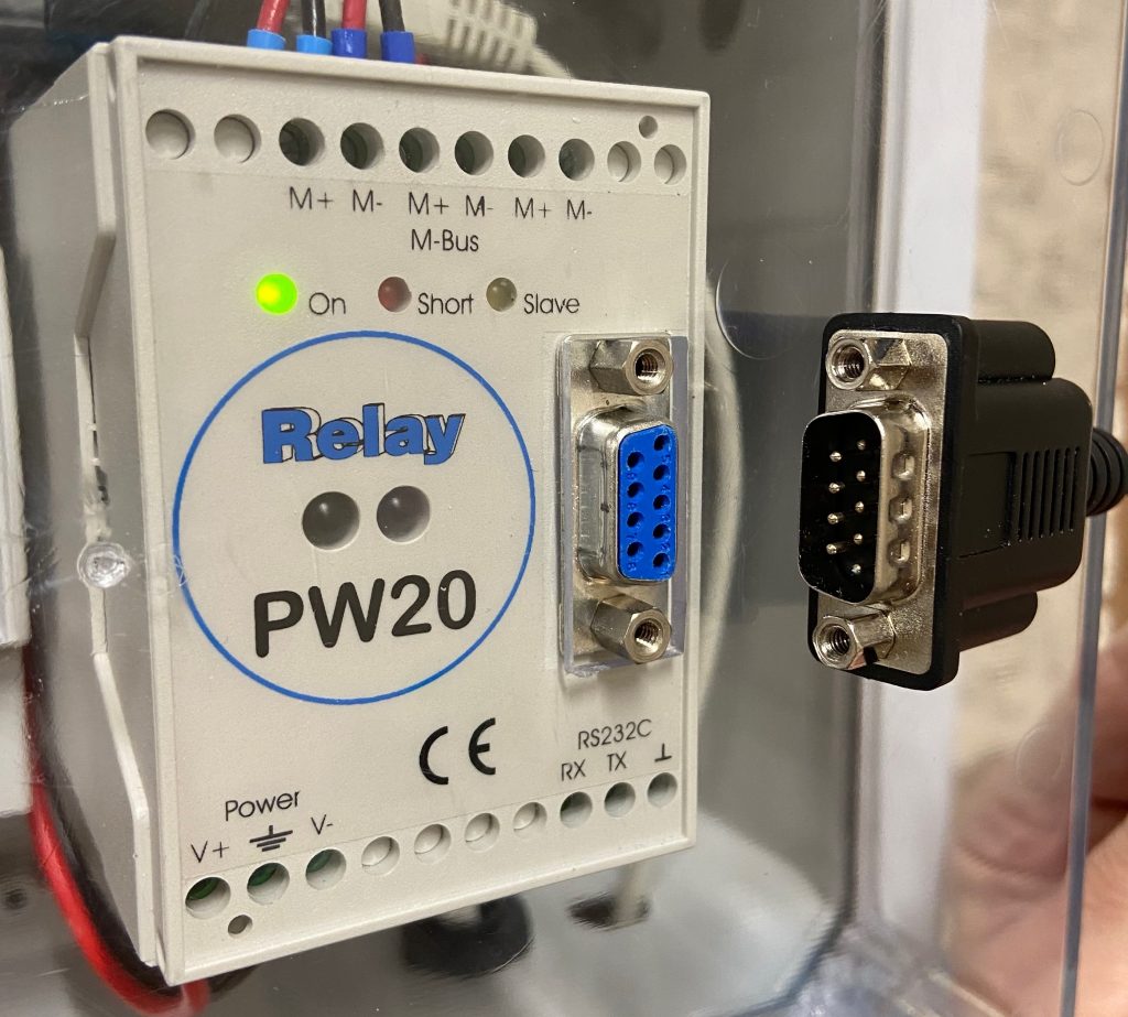
A recent situation was for the automated garage doors. Those are Hormann RollMatic 2 roller shutters and each one has a Hormann KNX Gateway attached to its HCP Bus. While these don’t provide a huge range of functionality, they do make it possible to open and close the roller shutters from the KNX Bus (e.g. using Home Assistant) and to trigger other actions when the shutters open and close.

The behaviour I wanted is that whenever one of the doors starts opening, it:

  • Switches on the two Indoor garage lights either side of that specific door
    • There are no windows in the garage and the garage doors are North-facing so it’s generally always desirable for the indoor lights to come on – though I’ll review that again in the Summer
  • Switches on the two Outdoor garage lights either side of that door
    • But only if it’s dark outside
  • Switches on a relay to tell the alarm system that a door is being opened

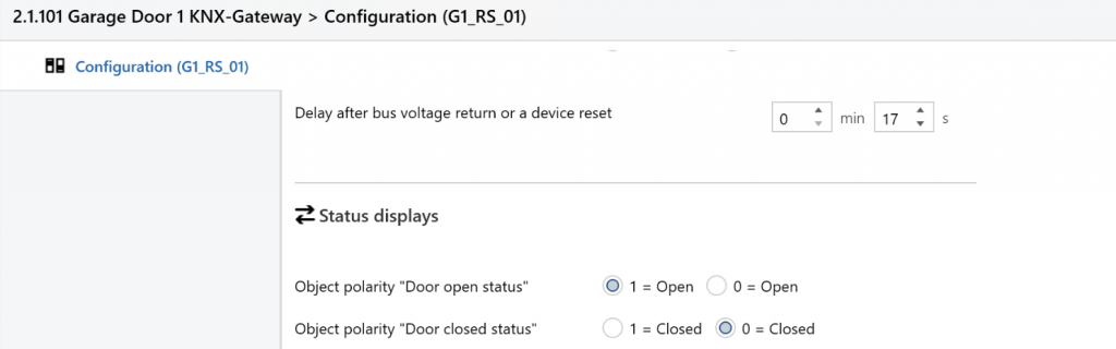
The Hormann KNX Gateway provides both a “Door open status” and a “Door closed status” output. At first glance “Door open status” looks like it will provide the necessary trigger but in fact that only changes state when the door is fully open – i.e. at the end of the motor travel. Fortunately there are configuration options to flip the “Object polarity” for both these outputs, and by selecting “Door closed status” to be “0 = Closed” (as shown below) that effectively becomes a ‘Not-Closed’ output, which changes to 1 as soon as the door starts opening.

Part of the KNX ETS Configuration screen for the Hormann KNX Gateway, showing the two “Object polarity” options

The Hormann KNX Gateways were a relatively late addition to the installation, due to availability issues, so I’d previously configured separate KNX Group Addresses for each of the Lights to enable manual control using the Home Assistant app.

The mistake I made was to link the Hormann KNX Gateway’s “Door Not Closed” output to the multiple Group Addresses I’d already configured – and the problem is that only one Group Address can be configured as the “Sending” destination for an output object. Initial testing showed that my multiple-GA configuration sort-of worked – e.g. the indoor lights initially came on when a door opened – but once the other targets were configured the indoor lights stopped working.

The fix was to link all of the lighting relay channel switches directly to the same Group Address as the “Door Not Closed” output, so the latter is only “Sending” to that one GA. There are still dedicated Group Addresses for the lights, for use with Home Assistant, but those are no longer targets for the “Door Not Closed” output.

To complete the picture, the “But only if it’s dark outside” logic is addressed using a Group Address which tracks whether it is “Daylight” or not, and configuring that as a “Lock” for the relay channels connected to the Outdoor lights. When the Daylight GA is ‘On’ the Lock is active and the status change from the “Door Not Closed” output gets ignored for the Outdoor lights. The setting and resetting of the Daylight GA is performed using the existing Home Assistant Automation rules which run at Sunrise and Sunset (although using a KNX ‘Twilight’ sensor would be an alternative and more natively-KNX way of achieving that).

The only remaining minor issue is that some of the Indoor lights switch off when one of the garage doors gets to be fully closed – which is annoying when planning to continue working inside the garage with all the doors closed. That means using the light switch (or Home Assistant) to turn them all on again. In principle, it would be possible to use the motion sensors which are part of the alarm system to control (some of) the lights, but that integration isn’t currently in place.

Itron Water Meter Cyble M-Bus Adaptors for the Outbuildings

For various reasons it proved difficult to set up the Cyble M-Bus adaptors for the two Itron water meters in the Outbuildings. (There are already three nearly-identical water meters with Cyble M-Bus adaptors in the House, which are working perfectly.)

The first challenge was sourcing the Cyble M-Bus reader heads. The original plan was for the building contractor’s plumber to source these along with the Itron Aquadis+ water meters (which is what happened last time, for the units in the House) but while the plumber had no issue obtaining the meters they struggled with the Cyble units and we all agreed I would source those myself, since I knew which specific ones I needed (and I assumed they would be easy enough to get hold of). The Cyble Pulse-Output reader heads are readily available but for some reason the M-Bus variants are more difficult to source. The best supplier for these in the UK seems to be MWA Technology, who list them on their website as Itron Cyble M-Bus For Aquadis and Woltex but MWA are not geared up to dealing with individual customers and while they were helpful they said they’d have to get their finance team to set me up with an Account – which sounded like a lot of work for both them and me. They suggested various distributors, some of which I’ve used before, but those just pointed me back at MWA. In the end I was successful in sourcing two of the Cyble M-Bus readers from metermarket.co.uk who happened to have a few in stock, though these days they specialise in Electricity meters rather than Water meters.

The second challenge was getting these to report meter readings via M-Bus. I knew I’d have to set the M-Bus addresses for each adaptor and I’d forgotten that these are supplied set to Primary Address 0 (for some reason I remembered them defaulting to Primary Address 1) and I wasn’t sure whether the RS-232 connection to the Relay PW20 M-Bus interface needed any sort of adaptor cable or not.

The PW20 is fitted with a Female DE-91 connector and the USB-to-RS-232 lead (with an FTDI interface chip) has a Male DE-9 connector – so that should all work fine but they both have fixing nuts which clash, preventing the plug from being inserted.

A minor annoyance – the electrical connectors will mate directly – except both sides have the nuts fitted

The nuts are rigidly fixed into the connector on the lead – and they secure the connector to the front of the PW20 (with further nuts inside the case which would be hard to re-attach.) Creative use of two Gender Change adaptors with the locknuts removed seems to work OK. (Ordinarily I use a different FTDI cable with a replacement DE-9 head, which has locking screws rather than locking nuts.)

After trying various cabling options and checking the default Primary Address I was able to program a unique Primary Address (and the meter serial number and initial meter reading) using the Actaris Cyble M-Bus Configuration Tool (CMCT) software. The devices then responded to the normal M-Bus polling code – but with ‘short’ responses, missing any meter readings. Comparing these responses to the ones from the ‘good’ meters in the House, the <Status>10</Status> is the only material difference in the <SlaveInformation> record (the meters in the House report <Status>00</Status>).

$ mbus-serial-request-data -b 2400 /dev/ttyUSB0 6
<?xml version="1.0" encoding="ISO-8859-1"?>
<MBusData>

    <SlaveInformation>
        <Id>22001387</Id>
        <Manufacturer>ACW</Manufacturer>
        <Version>20</Version>
        <ProductName>Itron CYBLE M-Bus 1.4</ProductName>
        <Medium>Water</Medium>
        <AccessNumber>20</AccessNumber>
        <Status>10</Status>
        <Signature>0000</Signature>
    </SlaveInformation>

    <DataRecord id="0">
        <Function>Manufacturer specific</Function>
        <Value>00 22 00 13 87 CF EA 03 07 01 12 03 0B</Value>
        <Timestamp>2026-01-24T13:02:29Z</Timestamp>
    </DataRecord>

</MBusData>

Initially I wondered whether the meters needed to ‘see’ a certain amount of water usage in order for a reading to be reported, but even running a couple of hundred litres through one of them didn’t change the response.

There aren’t many functions available in the CMCT software, but one of those is Reset alarms and running that did the trick, with the XML response changing to the expected:

$ mbus-serial-request-data -b 2400 /dev/ttyUSB0 6
<?xml version="1.0" encoding="ISO-8859-1"?>
<MBusData>

    <SlaveInformation>
        <Id>22001387</Id>
        <Manufacturer>ACW</Manufacturer>
        <Version>20</Version>
        <ProductName>Itron CYBLE M-Bus 1.4</ProductName>
        <Medium>Water</Medium>
        <AccessNumber>40</AccessNumber>
        <Status>00</Status>
        <Signature>0000</Signature>
    </SlaveInformation>

    <DataRecord id="0">
        <Function>Instantaneous value</Function>
        <StorageNumber>0</StorageNumber>
        <Unit>Fabrication number</Unit>
        <Value>22001387</Value>
        <Timestamp>2026-01-25T15:08:47Z</Timestamp>
    </DataRecord>

    <DataRecord id="1">
        <Function>Instantaneous value</Function>
        <StorageNumber>0</StorageNumber>
        <Unit>cust. ID</Unit>
        <Value>0Z        </Value>
        <Timestamp>2026-01-25T15:08:47Z</Timestamp>
    </DataRecord>

    <DataRecord id="2">
        <Function>Instantaneous value</Function>
        <StorageNumber>0</StorageNumber>
        <Unit>Time Point (time &amp; date)</Unit>
        <Value>2026-01-25T15:07:00</Value>
        <Timestamp>2026-01-25T15:08:47Z</Timestamp>
    </DataRecord>

    <DataRecord id="3">
        <Function>Instantaneous value</Function>
        <StorageNumber>0</StorageNumber>
        <Unit>bat. time</Unit>
        <Value>4010</Value>
        <Timestamp>2026-01-25T15:08:47Z</Timestamp>
    </DataRecord>

    <DataRecord id="4">
        <Function>Instantaneous value</Function>
        <StorageNumber>0</StorageNumber>
        <Unit>Volume (m m^3)</Unit>
        <Value>3515</Value>
        <Timestamp>2026-01-25T15:08:47Z</Timestamp>
    </DataRecord>

    <DataRecord id="5">
        <Function>Instantaneous value</Function>
        <StorageNumber>0</StorageNumber>
        <Unit>Volume (m m^3)</Unit>
        <Value>0</Value>
        <Timestamp>2026-01-25T15:08:47Z</Timestamp>
    </DataRecord>

    <DataRecord id="6">
        <Function>Instantaneous value</Function>
        <StorageNumber>1</StorageNumber>
        <Unit>Volume (m m^3)</Unit>
        <Value>0</Value>
        <Timestamp>2026-01-25T15:08:47Z</Timestamp>
    </DataRecord>

    <DataRecord id="7">
        <Function>Manufacturer specific</Function>
        <Value>1F 02 00</Value>
        <Timestamp>2026-01-25T15:08:47Z</Timestamp>
    </DataRecord>

</MBusData>

Another thing to note is that by default, the Volume Index in CMCT was formatted as NNNNNNN.N m3 whereas the physical display on the meter shows NNNNN.NNN m3 – and they need to match in order for the readings to be accurate. While it’s not possible to add three decimal places with 7 leading digits (i.e. NNNNNNN.NNN) it is possible to delete two of the leading digits in order to add three decimal places.

Finally, after having had issues with the Cyble reader heads getting dislodged in the past (resulting in them missing some updates from the meters) I wanted to pay more attention to fixing them more securely. I rather expected the new units to come with fixing screws, but they didn’t – but the one screw I had for the meters in the House fitted fine. That’s an M4 x 25mm Cheese Head machine screw, made of Nylon. Note it’s necessary to destructively ‘unscrew’ a plastic piece covering the brass insert that the screw engages with. On the newer meters this projects roughly 5mm above the surface and prevents the Cyble adaptor being fitted until it is removed, whereas on the older meters it’s recessed below the surface and only prevents the screw from being inserted. The removal of this plastic piece is cryptically shown at W2 ‘B’ in the Installation Instructions (attached below).

  1. Sometimes mistakenly called a DB-9 – but the ‘B’-size connector shell is generally only used with 25-pin connectors ↩︎