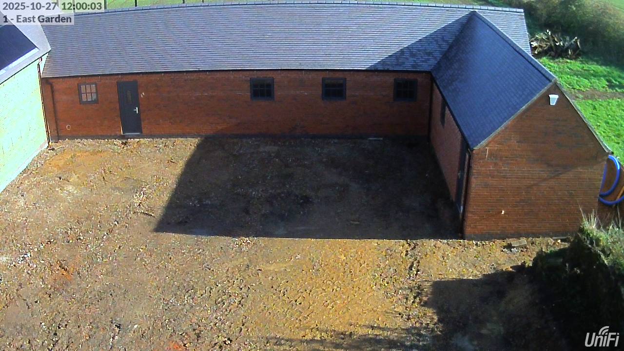
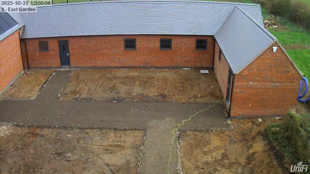
Home Battery Storage Sizing Calculations

The House has a 5.4 kWp solar PV installation dating from 2017 but no battery storage. The Outbuildings will be getting an 11 kWp solar PV installation along with battery storage. The question is: what’s the ‘optimum’ size of battery storage to install?

Winter-time Scenario

To some extent, this depends on the electricity tariff in use, but as a starting point let’s assume a tariff like Intelligent Octopus Go, which has a very low rate (currently 7p per kWh) for 6 hours a day (23:30 – 05:30) and a much higher rate for the remaining 18 hours.

A good approach is to size the batteries to be able to meet all of the electricity demand during the ‘peak’ hours by charging the batteries during the ‘off-peak’ hours. The worst case for that is in winter, when the heat pump is running and there’s little solar PV generation to offset the need for import during the peak hours.

(It’s fair to assume that electric car charging will be scheduled to happen in the ‘off-peak’ hours so it’s not necessary to account for charging electric car batteries from the house battery in this scenario.)

Looking back at the electricity bills for the 2024-25 winter period, the average daily import during ‘peak’ times was fairly consistently 19 kWh – i.e. just over 1kW on average for the 18 hours.

Clearly the Outbuildings will add to the electrical load and so increase that figure. Let’s assume a combined average load of 1.5 kW, requiring 27 kWh in total for the 18 hour peak-rate period (i.e. allow a ‘budget’ of about 450 W for the Outbuildings, to cover the MVHR unit, the Heat Pump, the IT kit etc.)

If the batteries are 100% charged at the start of the ‘peak’ period, and if they’re configured to permit discharge to 0% (which would be unusual) 27 kWh of battery capacity would just be able to satisfy the demand.

In practice, it is customary to limit the battery discharge to about 20% of capacity (to maintain a reserve in case of a grid failure – and also to help prolong the life of the battery, by not discharging it all the way to 0% on a daily basis) so 27 kWh of ‘usable’ capacity would need a battery set-up with a ‘nominal’ capacity of 33.75 kWh (80% of 33.75 kWh = 27 kWh). That’s 2.5 x 13.5 kWh battery modules.

If the combined average load was more like 1.8 kW (rather than 1.5 – i.e. allowing a budget of 750 W for the Outbuildings), that would equate to a battery set-up with a nominal capacity of 40.5 kWh – which would be 3 x 13.5 kWh battery modules.

Summer-time Scenario

The other key role for the battery storage is to be able to accept the ‘excess’ solar generation during the summer. The need for this arises because the maximum export permitted back to the grid (5.5 kW) is much less than the installed solar PV generation capacity (16 kWp).

The basic approach is to have the solar PV dump the excess power into the batteries in the middle of the day then export that back to the grid later in the day / overnight to stay under the maximum permitted export limit while still getting paid for the export.

On occasions when the solar PV array is operating at its absolute maximum peak capacity, we’re looking at:

  • 16 kW of solar PV generation
    • 11 kW from the ‘new’ panels on the Outbuildings plus 5 kW from the ‘old’ panels on the House
  • 0.5 kW of on-site ‘base load’ consumption
    • This might be higher – especially if electric car batteries need charging or the hot water tank can accept power via its immersion heater element – but in the worst case of an unoccupied house the usage will be no more than about 500W
  • 5.5 kW of maximum-permitted Export to the Grid
  • 16 – 0.5 – 5.5 = 10 kW of ‘excess’ generation that has nowhere else to go, so will be used to charge the batteries (provided those are not fully-charged already)

Clearly if generation at this level were to persist for long then even large batteries would fill quickly, but the 16 kW figure is an absolute maximum that will only ever be reached for a few minutes at solar noon – and then only under perfect generation conditions (no cloud cover and relatively cool temperatures).

Experience with the existing solar PV array shows that the peak generation in mid-summer is roughly 80% of the declared kWp value (even on cloud-free days – because those tend to be too hot to achieve maximum efficiency) – here’s an example from 2022, for the existing 5.4 kWp array on the House (which after 5 years was probably operating around 5.2 kWp).

Solar PV generation plot from the SolarEdge dashboard at the summer solstice in 2022

To better model the solar generation profile, we can approximate it as a sine wave – since we know the area under a half-cycle of a sine wave from 0 to π is 2 x peak value. The same graph above with an overlaid sine wave is shown below.

Generation data for 2022-06-21 combined with a sine wave model

At the summer solstice, the sine wave crosses the X axis at about 06:15 and about 19:45, which is 13.5 hours rather than π hours, so we need to multiply by 13.5 / π = 4.297, hence the predicted ‘cloudless day’ generation at the summer solstice is 2 x 4.297 = 8.59 times the peak value.

(This calculation closely matches the real-world data from the first graphic: on nearly cloud-free 2022-06-21 the existing solar array generated a total of 35.46 kW of electricity, with a peak of 4.1 kW.)

Since any generation less than 6 kW will be either consumed on-site or can be exported to the grid, the ‘problem’ is the generation above 6 kW, which will happen for up to about 9.25 hours (as shown in the graphic above). If the peak generation is 13 kW (i.e. 7 kW more than 6 kW) the total ‘excess’ generation during those 9.25 hours is: ( 9.25 / π ) x 2 x 7 = 41.25 kWh.

To store absolutely all of this generation would require batteries with a nominal capacity of 41.25 / 0.8 = 51.56 kWh – which would mean 4 x 13.5 kWh battery modules (for 54 kWh). However, experience shows that such ideal generating conditions rarely happen – for example the days either side of the summer solstice in 2022 were rather less good:

Total daily generation for 2022-06-21 and 3 days either side

On that basis, it would be unreasonable to design for this worst case scenario and instead tolerate some curtailment of solar PV generation if the battery ever gets full.

A further consideration is that the Outbuildings will have an Air-to-Air heat pump system which is capable of Cooling as well as Heating. On the very hottest days of the year, it might be sensible to run the heat pump in Cooling mode, which will consume some of the solar PV generation during the hottest part of the day.

Conclusion

It’s looking as if 3 x 13.5 kWh battery modules is the ‘best’ answer. There are technical merits in at least two battery modules (higher AC charging limits, for example) and the third module would provide enough capacity to run the site all-day in winter by charging the batteries overnight, at off-peak rates.

Another way of looking at things is to review the cost-effectiveness of the third battery pack:

  • 3 x 13.5 kWh battery packs, with a nominal capacity of 40.5 kWh / usable capacity of 32.4 kWh would be able to support all the anticipated winter-time consumption at 7p per kWh
  • 2 x 13.5 kWh battery packs, with a nominal capacity of 27 kWh / usable capacity of 21.6 kWh would require the import of ( 32.4 – 21.6 ) = 10.8 kWh at peak rate, costing an extra 18.4p per kWh, or £2 per day

£2 per day for every day in the heating season (6 months) is £365 per year saved by having the third battery pack.

In addition, there’s the ability to store additional excess solar generation on sunny days, getting paid to export that (at typically 15p per kWh) rather than not generating it at all. It’s harder to estimate how on how many days an extra 10.8 kWh could be generated, stored in the batteries and exported later, but if that was 150 days that’s an extra £243 – so potentially a total saving of around £600 per year from the third battery pack.

M-Bus Water Meter Reading Discrepancies

There are three water meters in the house:

  • One on the incoming Cold water supply
  • One on the cold water supply to the bottom of the hot water cylinder, which measures the Hot water consumption (and needs to be subtracted from the incoming cold meter reading to leave the cold water usage)
  • One on the separate cold water supply to the potential-future-rainwater-harvesting pipework
    • This third one is actually fed from the incoming mains supply outside the house but might in future be connected to a rainwater harvesting system
    • Within the house, the pipework connected to this meter feeds the toilets, the washing machine and the outside taps (i.e. all the appliances which are permitted to be fed with harvested rainwater)

These meters are in addition to the water company’s ‘revenue’ meter and could be considered excessive, but:

  • The water company’s meter is about 600 metres away from the house so there’s a lot of underground pipework that could potentially leak (and which runs through fields which get ploughed) and it’s good to be able to cross-check the meter readings in case any leaks develop
  • It’s useful to be able to compare the Hot water usage with the Cold water usage – and to see how much of the water usage could potentially be displaced by rainwater harvesting
    • This is especially pertinent as I firm-up the specification for the Outbuildings, to be constructed as part of “Phase 2” of the building work, and compare the cost of a rainwater harvesting system with the potential savings

The three internal meters have M-Bus readers fitted and are automatically read every minute – along with all the other M-Bus readers in the house. (Reading so often is completely over-the-top for Water meters, but not for e.g. Electricity meters, and it’s easiest just to read all the meters on every read-cycle than to mess about reading different meters at different intervals.) Then, every month, I manually record the monthly meter readings (as reported by M-Bus) into a spreadsheet to look at a summary-level view and monitor trends in usage.

Over the past couple of months I’ve noticed the ‘rainwater’ meter showing much higher readings than before, which seemed odd. On the 1st of May, the usage was up a bit; on the 1st of June the usage was up a lot – roughly 10 x the usage in February, for example. Initially I suspected a leak but on checking further it was clear the meter reading wasn’t changing unless there was obvious water usage.

Then I realised what was happening: it’s not that the meter is now reporting ‘high‘ – it’s that the meter has previously been reporting ‘low‘. The dials on the meter are showing 114 m3 but the M-Bus adaptor is reporting 85 m3. Plotting a graph of the meter readings over time (that I don’t normally do) makes it clear that something went wrong around the end of April 2022 that got fixed around the middle of April 2024.

‘Rainwater’ Water Meter readings, early 2022 through to mid 2024

I know what I did to ‘fix’ it – I’d been checking the details of the meter to be able to match it in the new building and removed and re-fitted the M-Bus adaptor. I don’t know what I did to ‘break’ it – but given that some readings were still coming through I presume the adaptor was knocked slightly out of position. (If it had stopped reading completely I would have spotted it.)

The meters are Itron Aquadis models with Cyble M-Bus adaptors that slide into some slots on the front of the meters – but they don’t clip into place hence they’re reliant on friction (or gravity) holding them in position, and they can get knocked.

Now the problem is that the internal registers on the M-Bus adaptor don’t match the dials on the meter and there are no buttons or display on the M-Bus adaptor to make any adjustments – so it’s a case of using the Cyble M-Bus software that I originally used to set the M-Bus IDs to re-set the reading from the dials.

This was easy enough – once I’d worked out the Cyble M-Bus software needs to run as Administrator. Changing the reading is as simple as clicking on the digits and entering the new reading.

Screenshot of Cyble MBus v1.4 software

I’d forgotten these adaptors have the option to report against a Leakage threshold value; what’s not clear is how the detection of a ‘leak’ gets reported – there no obvious ‘leakage’ field in the XML data record that comes back to the M-Bus reader.