
Any heat pump’s Weather Compensation control algorithm is fundamentally reliant on an accurate sensor input for the outdoor temperature1. For the NIBE F1145 Ground Source Heat Pump this comes from a NIBE-branded temperature sensor module – the same as the one for the indoor temperature – which contains a simple thermistor, wired back to two terminals on the heat pump’s control board.
The heating is not yet running this year (the house is currently maintaining 22.5C without it) but I have noticed that the outdoor sensor is reporting low readings – e.g. just 0.4 C at 08:00 one morning when an independent but adjacent outdoor temperature sensor was reporting 8.4C (which also matched the BBC weather forecast). In previous years, these two sensors consistently reported almost identical readings. With a Negative Temperature Coefficient (NTC) thermistor, any additional resistance in the sensor circuit shows up as a lower temperature reading, suggesting that there is a high resistance in the wiring somewhere – something like an extra 10 kOhms – or perhaps the sensor element itself is faulty.
I don’t run the heating in ‘pure’ Weather Compensation mode since the house is prone to receiving passive solar gain in the Winter (which is A Good Thing – free heating!) so it also uses the indoor temperature sensor to decide on the target heating flow temperature. This behaviour would tend to compensate for any issues with the outdoor sensor – but I’d still prefer to have that working correctly.
It is important for the outdoor sensor to accurately report the temperature of the outdoor air and in particular it should be shielded from the sun – which means locating it on the North side of the building and ensuring the rising Winter sun does not heat it early in the morning. With this in mind it had been mounted under the canopy over the front door and rather than being placed with the backplate vertical, it had been mounted horizontally. That made for a neat installation but meant the cover acted as a very effective ‘cup’ and would hold a pool of water if any got in there.
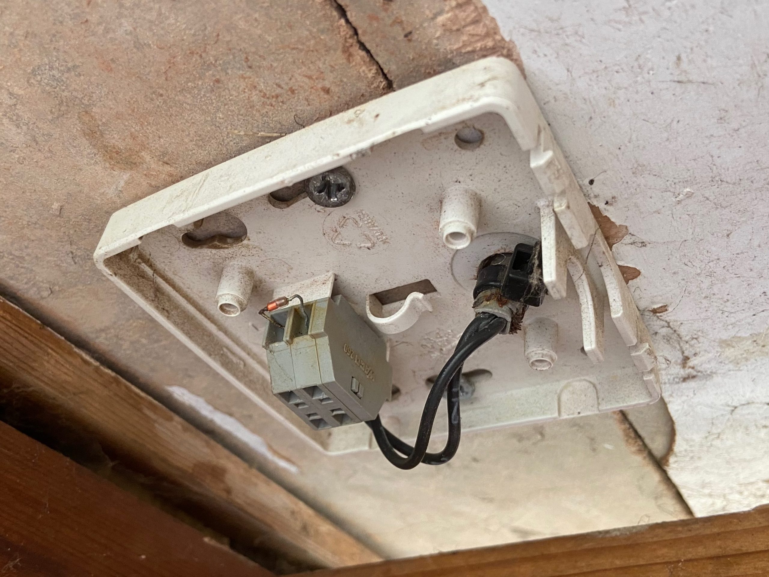
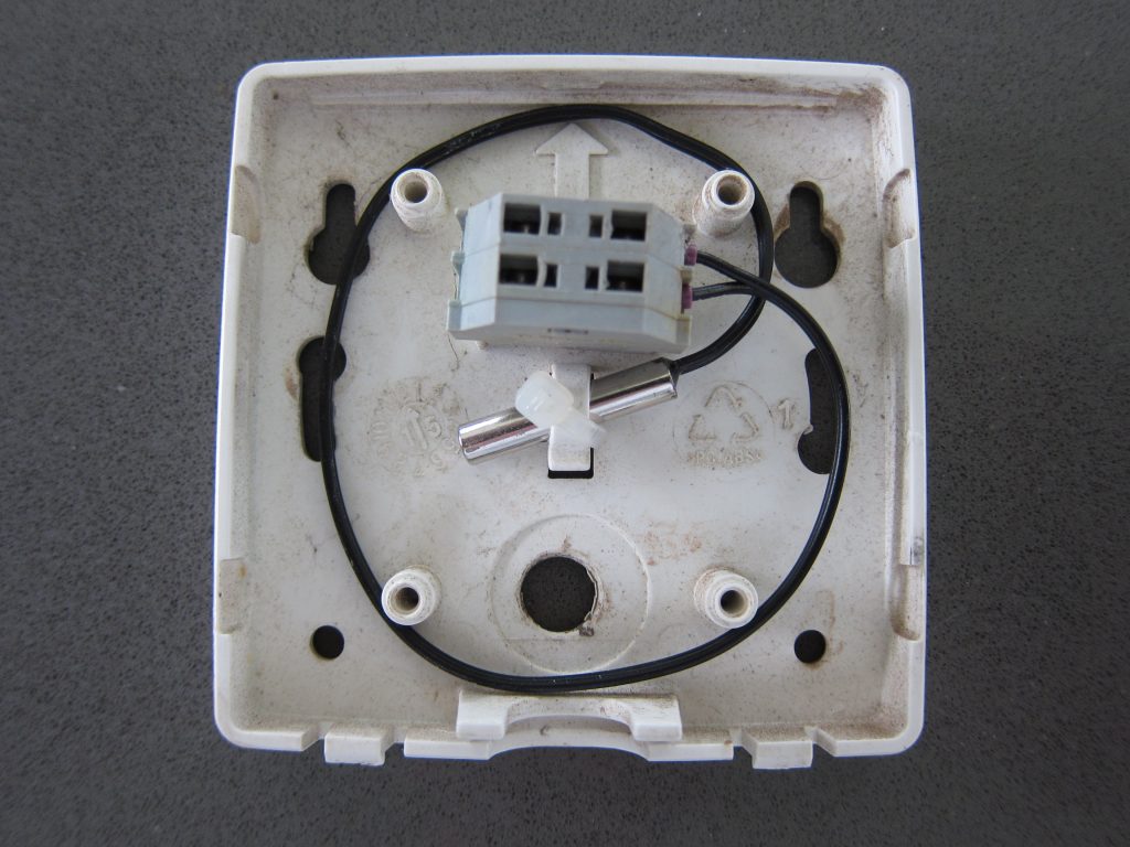
The outdoor sensor element has admittedly had a hard life over 10 years, having been immersed in water several times. Presumably as a consequence of this there is some corrosion visible on the thermistor leads. Re-seating all the contacts didn’t seem to help (but removing and refitting the sensor element did trigger an Alarm message from the Heat Pump, saying the BT1 sensor was disconnected).
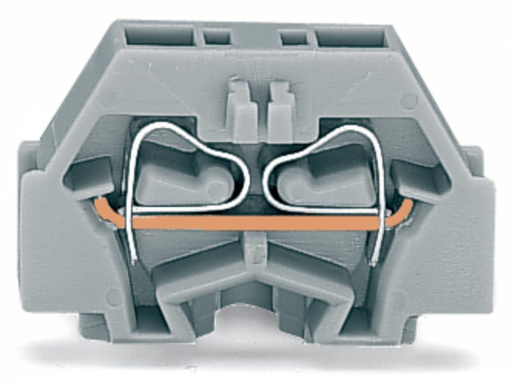
It wasn’t immediately obvious how to release the WAGO 260 connections but this cross-section shows that the springs are compressed by pushing down vertically through the rectangular access holes in the top; the wires slide in from the sides under the horizontal copper bar.
Complete replacement sensor modules are available. It appears that the original unit had NIBE Part Number 218845 but that has been upgraded to the similar-looking RTS 40 which now has an ‘encapsulated’ thermistor – this change tending to indicate there’s a known issue with corrosion on the original unencapsulated thermistors when used outdoors, enough to warrant a design change.
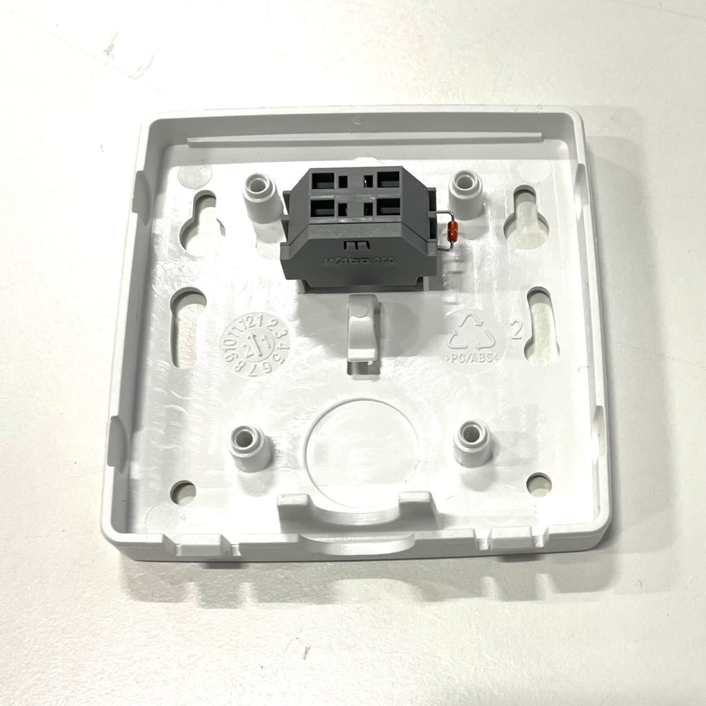
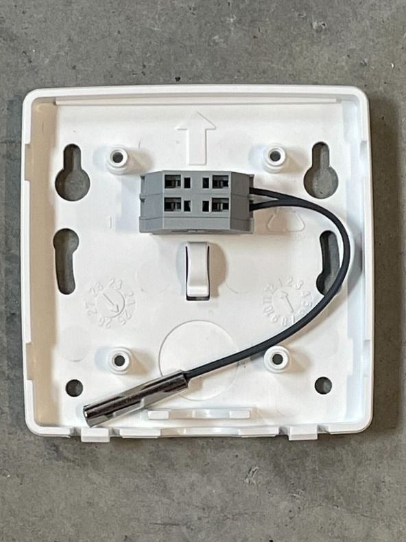
A complete new RTS 40 module is available from several suppliers, for example:
- JS Energi want £30.10 + VAT for the Room sensor RTS 40 NIBE, usage for both outdoor and room
- This price seems fairly reasonable but delivery is extra (from Sweden?) and is expensive
- UK supplier Heat Pump Parts want £58.32 + VAT for the NIBE RTS 40 OUTDOOR / INDOOR ROOM SENSOR – 318828 (218845 + 060514)
- Nu-Heat want £120.25 + VAT for their HPATS-C – NIBE air temperature sensor, for indoor and outdoor use which looks like the exact same unit
Since I already have the enclosure and the WAGO 260 connector block, might it be possible to just replace the thermistor element? That’s surely a commodity component, not specific to NIBE.
The resistance values for the sensor are documented in the installer manual, including the specification of exactly 10 kOhms at 25C. That’s certainly fairly standard for an NTC thermistor, with the main other variable being the ‘Beta’ (sometimes just ‘B’) value – effectively the gradient of the temperature / resistance relationship.
A very common Beta value is 3435K but there are also thermistors with values of 3950K, 4190K etc. Some of the 3950K ones available to purchase look very much like the original ‘bare’ thermistor, and these are also available encapsulated in a stainless steel tube – very much as shown in the second NIBE photo above.
The Wikipedia page for Thermistor has an equation for the Beta calculation which can be used to compare with the values printed in the NIBE installer manual. Testing a few data points in this equation showed that the listed values do indeed correspond to a 3950K 10kOhm @ 25C NTC thermistor.
Encapsulated 3950K 10kOhm NTC thermistors with 1% accuracy are available for a couple of pounds from eBay, which is cheap enough to give one a try – taking the precaution to check their resistance first, using a multimeter. Even if the behaviour is a little off-spec, it will surely be better than the old, corroded sensor element (which actually fell apart when I came to replace it).
Suitable replacement sensors should show up in an Internet search for: NTC 10K 1% 3950K thermistor waterproof probe cable. A 30cm cable is more than sufficient but a longer one would be OK too. These typically come with a small white plug attached which I cut off and replaced with wire-end ferrules (the purple cap of these is just visible in the photo below). The bare wires are thin and I would not trust them straight into the WAGO 260, without a ferrule (though I use ferrules on all stranded cable connections).
Be careful to avoid the similar-looking DS18B20 temperature sensor which might get returned by some search engines (looking at you, Google); those use digital signalling and are not compatible.
An encapsulated thermistor element is going to respond more slowly to changes in temperature than the original ‘bare’ sensor but there is already some averaging applied to the sensor reading by the heat pump’s controller. The time period over which this averaging is applied can be adjusted in the controller’s menu: this is “Filtering time” in screen 4.9.2, described as:
the time over which the average temperature is calculated. If you select 0, the present outdoor temperature is used.
The factory-default Filtering time is 24 hours and presumably this should be reduced a little to cater for the built-in ‘filtering’ effect of the encapsulated thermistor. Both the instantaneous and the average outdoor temperatures are reported by the myUplink API:
    ...
    Parameter Id:            40004
    Parameter Name:          Current outd temp (BT1)
    Parameter Unit:          °C
    Parameter Value:         18.3
    Parameter Display Value: 18.3°C
    ...
    Parameter Id:            40067
    Parameter Name:          Average outdoor temp (BT1)
    Parameter Unit:          °C
    Parameter Value:         18.8
    Parameter Display Value: 18.8°C
    ...
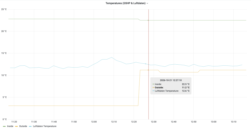
With the sensor element replaced, the heat pump started reporting much better-looking temperature readings. The graph below shows the step in the orange line when the sensor was replaced at 12:22, with the Outside sensor reading jumping from 3.1C to 11.2C – much closer to the Luftdaten Temperature (which is probably slightly high; a sensor in an open-to-the-elements store room shows 11C).
It’s early days but that looks like a successful repair. Now I know how badly the original sensor had corroded I’d recommend this as preventative maintenance – or at least having a replacement sensor element on-hand.
- For people not familiar with Weather Compensation control, this predicts the heat being lost by the building by looking up the outdoor temperature on the configured WC Curve, reading off the corresponding value for the target heating flow temperature. The system then runs to deliver that target flow temperature (on average) to offset the heat loss and hence maintain a stable indoor temperature from the lowest possible flow temperature, thus maximising efficiency. If the controller thinks it’s significantly colder outside than it actually is, it will push too much heat into the building. ↩︎