DHCP Topology for Networks in the House and Outbuildings

There are some network Subnets which are local to the Outbuildings, with a Routed (Layer 3) connection back to the House.1 To field DHCP requests for Hosts on these Subnets, there needs to be something local to those subnets to receive the DHCP packets broadcast by clients.

Plan A was to use a separate instance of the dnsmasq DHCP / DNS server running on the Firewall / Router in the Outbuildings, configured with its own DHCP Ranges and Host Reservations etc. and forwarding DNS requests to dnsmasq running on the Firewall / Router in the House, While this sort-of worked OK, there were some shortcomings:

  • Hosts in the Outbuildings can resolve DNS requests for Hosts in the House, since the House’s DNS server is ‘upstream’ – but Hosts in the House cannot resolve DNS requests for Hosts in the Outbuildings, since those DNS records are only present in the Outbuildings’ DNS server.
    • While this isn’t a show-stopper, it’s more convenient for all Hosts to be able to resolve DNS names for all other Hosts.
    • I guess a workaround would be to point all the Hosts in the House to the Outbuildings‘ DNS server – but that would be pretty clunky
  • DNS responses from the House’s DNS server to the Outbuildings’ DNS server are flagged as a “possible DNS-rebind attack” – because they map to RFC1918 ‘private’ address space. The default configuration of dnsmasq on OPNsense makes it difficult to process such requests; it’s difficult to turn off the checking for such attacks.

Plan B is therefore to run DHCP Relay agents on the Subnets in the Outbuildings instead, forwarding DHCP requests to and from dnsmasq in the House. As well as addressing the issues listed above, there are a few ‘softer’ benefits:

  • All of the DHCP configuration – of Ranges, Host Reservations etc. is now consolidated in one place – in the House’s dnsmasq configuration pages.
    • There’s just a small, one-time configuration required in the Outbuildings’ router configuration, for every Subnet that needs a DHCP Relay agent
    • While this means there’s a single point of failure for DHCP, the House’s router is a single point of failure for pretty much all of the network connectivity anyway
  • Since the House’s dnsmasq server is configured to set the DNS server record in DHCP leases to ‘the address of the DHCP server’, that has the side effect of having all DNS queries from the Outbuildings go direct to the House’s DNS server – without the need to run any sort of DNS relay in the Outbuildings.
    • The same applies for NTP

In order to implement this behaviour the DHCRelay Service needs to be configured on the Outbuildings’ Firewall / Router. (It’s installed by default but without any configuration entries it has no effect.) There needs to be one “Destination” DHCP server (the House DHCP server in this case) set up – and then every network Interface which needs DHCP Relay services needs to be aded to the list of Relays.

Screenshot of the DHCRelay Configuration on the Outbuildings’ Firewall / Router

Then, on the House’s Router / Firewall, the corresponding DHCP ranges need to be defined as part of the dnsmasq configuration. All of the relayed DHCP requests for clients in the Outbuildings appear on the BACK network interface (the backbone link between the two routers) so the various address ranges need to be specified against that one interface.

Screenshot of the Dnsmasq DNS & DHCP Configuration on the House Firewall / Router

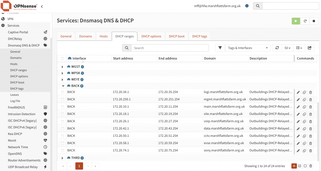
I think that’s all the configuration that is required. The relayed DHCP Request includes the IP address on which the Relay received the DHCPDISCOVER packet, which is enough to let the DHCP Server select from the appropriate address range (of the many ranges configured against the BACK interface).

  1. There are other network Subnets which need to be ‘stretched’ across both buildings. This is either because devices rely on Layer 2 continuity across the whole network (as is the case for the Paxton access control intercom system) or because they are supporting particular WiFi SSIDs and it needs to be possible for WiFi clients to roam from one Wireless Access Point to another while preserving the same IP address – even if these APs are in different buildings. All such networks are ‘bridged’ across the two buildings, so any DHCP traffic is naturally presented to the House DHCP server anyway. ↩︎

Alternative Firmware for GL.iNet GL-S20 Thread Border Router

By using non-vendor-managed firmware for the GL.iNet GL-S20 Thread Border Router, the Thread network is no longer limited to 3 or 4 devices and a few of the more minor annoyances with the standard firmware have been addressed:

  • The new Web UI no longer constantly requires the Admin password to be entered. Now it doesn’t ever require any password – which could be considered a security risk, although that can be addressed by restricting access to the TCP/IP network it’s connected to.
  • The Web UI now includes a Thread network Topology viewer which shows how the End Devices are connected to the Leader and any other Router nodes.

As a bonus, the TBR now supports Thread version 1.4 and it didn’t require the Thread network to be re-created following the installation of the new firmware; the previous details must have been saved in Non-Volatile Storage.

A very minor issue is that the wired network interface is using a very different MAC address and so is no longer matching the DHCP lease reservation assigned to the old one. Also, it was probably unreasonable to expect the Factory Rest button press to continue to restore the original factory firmware, so reverting to the GL.iNet-managed firmware would be more involved, perhaps most easily accomplished using the Windows firmware installation tool.

The source code for this alternative firmware comes from https://github.com/EPinci/ep-s20-otbr – where the ‘heavy lifting’ is done by links to the standard Espressif IoT Development Framework (IDF) and Thread Border Router (Thread-BR) SDK GitHub repositories. There’s then a fairly ‘thin’ add-on layer (based on some code previously released by GL.iNet) which is specific to the GL-S20 hardware.

The IDF runs perfectly happily on a Linux (Fedora) desktop which had no issues connecting over a USB cable to the USB-C port on the GL-S20. (The first installation of the alternative firmware must be done via a USB cable, although subsequent updates can be done over the network.)

The main issue I hit was a difference in the sizing of the Non-Volatile Storage (nvs) partition on the GL-S20: on my device this was previously sized at 0x10000 (ten thousand) bytes and by default the new firmware was mapping it as 0x6000 (six thousand) bytes, which triggered an error check for ‘no free pages’ (and a constant reboot cycle). Fortunately I’d saved a dump of the boot log when running the GL.iNet 2.0.1-B1 firmware which included the original partition table sizing, which I was then able to match with a small edit to partitions.csv. I added much more detail on this in Sizing of ‘nvs’ partition; ESP_ERR_NVS_NO_FREE_PAGES error (fixed) #1 in the Issues log on the GitHub repo.

The Thread Topology viewer is a feature that is almost essential for managing a Thread network with more than a very few nodes.

A screenshot from the Web UI for the Espressif Thread Border Router. The main body of the image shows a set of coloured circles connected by pale grey solid and dashed lines.
The largest circle is coloured Blue and the Key shows this is the 'Leader' of the Thread network. Two small Green circles are linked to the Blue circle by dashed lines, showing these are 'children' of the Leader.
A mid-sized Cyan circle represents a Router, linked to the Blue circle (Leader) by a solid line.
Three small Green circles represent Child nodes, connected to the Router by dashed lines.
Example of the Thread Network Topology view

The example Topology view above shows the Thread network Leader (the GL-S20) in Blue, with one Router (an IKEA GRILLPLATS smart plug) in Cyan. The ‘Child’ (i.e. non-Router) devices are in Green.

This Topology view introduces a set of node identifiers I had not come across before; IDs like 0xb402 are Thread network Routing Locator (RLOC) identifiers – strictly speaking RLOC16 identifiers (since these are just the last 16 bits of the full RLOCs) which identify the placement of nodes within the Topology graph. It is implicit in the naming that Node 0xb402 is a Child of Router 0xb400. Clearly these identities must change as the Topology changes – which is why alternative identifiers are also in play.

As yet I’ve not tried Commissioning a new Matter-over-Thread device with the TBR running this alternative firmware, but given that all the Thread credentials appear to have been preserved there’s no reason why that shouldn’t work the same as before.